Grounding nail

A grounding nail and ground drilling technology, which is applied in the field of grounding nails, can solve the problems of inconvenient construction and maintenance, discounted effect, and infirmity, so as to increase electrical conductivity and corrosion resistance, save time and effort to tighten and disassemble, and increase electrical conductivity Effect

Inactive Publication Date: 2020-03-06
STATE GRID CORP OF CHINA +1
View PDF6 Cites 5 Cited by
  • Summary
  • Abstract
  • Description
  • Claims
  • Application Information

AI Technical Summary

Problems solved by technology

The length of this grounding device cannot be changed, and it is needle-shaped. The locking mechanism used is more suitable for relatively hard soil conditions. It does not work well in loose soil, and it needs to be nailed deeper into the ground under special conditions. At this time, the length of the grounding device cannot be changed
[0005] The above two inventions have better effects when used in general or relatively hard soil conditions, but the effect is obviously not good enough in loose soil areas
And when we use the existing grounding nails in normal work, the effect is better when the soil is normal or hard, but when it comes to areas with loose soil, the effect is greatly reduced. The effect is not good, and it is inconvenient to use when facing different soil conditions and need to increase or decrease the depth of burial in the ground. Because the grounding nails cannot change the length, it is necessary to bring various types of grounding nails, which brings a lot of troubles for construction and maintenance in loose soil areas. Inconvenience and safety hazard

Method used


Image

  • Grounding nail
  • Grounding nail
  • Grounding nail

Examples


Embodiment 1

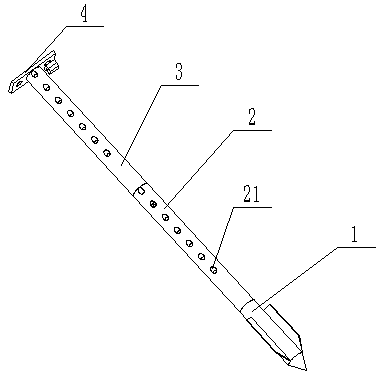
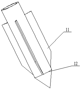
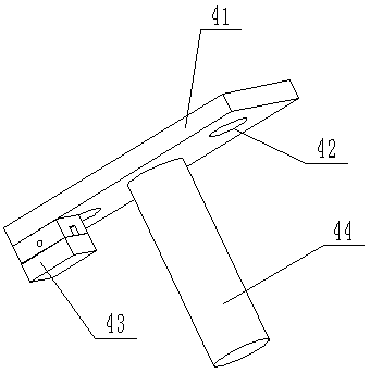
[0049] According to attached figure 1 , attached Figure 4 , attached Figure 5 And attached Figure 7 A grounding nail is shown, including a ground-drilling guide head 1, a base rod 2 detachably connected with the ground-drilling head guide head 1, and a striking device 4 detachably connected with the base rod 2; the ground-drilling guide The head 1 includes a drill body 12 and blades 11 evenly distributed on the outer surface of the drill body 12; the ground-drilling guide head 1, the basic rod 2 and the striking device 4 are sequentially connected. The ground-drilling guide head 1 is tapered as a whole with a blade 11, and the base rod 2 is a hollow structure; the detachable connections are threaded connections. The beating device 4 includes a beating plate 41, a joint 44 arranged on the lower surface of the beating plate 41, and a clamping device 43 arranged on one side of the joint 44; two ends of the beating plate 41 are provided with Lifting hole 42; Described snap-...

Embodiment 2

[0053] According to attached figure 1 , attached Figure 4 , attached Figure 5 And attached Figure 7 A grounding nail is shown, including a ground-drilling guide head 1, a base rod 2 detachably connected with the ground-drilling head guide head 1, and a striking device 4 detachably connected with the base rod 2; the ground-drilling guide The head 1 includes a drill body 12 and blades 11 evenly distributed on the outer surface of the drill body 12; the ground-drilling guide head 1, the basic rod 2 and the striking device 4 are sequentially connected. The ground-drilling guide head 1 is tapered as a whole and has a blade 11, and the base rod 2 is a hollow structure; the detachable connection relationship is a threaded connection; the hitting device 4 includes a hitting plate 41, which is arranged on the hitting plate The joint 44 on the lower surface of 41 and the clamping device 43 arranged on one side of the joint 44; the two ends of the striking plate 41 are provided wit...

Embodiment 3

[0057] According to attached figure 1 , attached Figure 4 And attached Figure 7 A grounding nail is shown, including a ground-drilling guide head 1, a base rod 2 detachably connected with the ground-drilling head guide head 1, and a striking device 4 detachably connected with the base rod 2; the ground-drilling guide The head 1 includes a drill body 12 and blades 11 evenly distributed on the outer surface of the drill body 12; the ground-boring guide head 1, the base rod 2 and the striking device 4 are sequentially connected; the base rod 2 and the growth Water holes 21 are all arranged on the pipe 3; the water holes 21 are upward oblique holes; The clamping device 43 on one side of the joint 44; the two ends of the striking plate 41 are provided with lifting holes; the clamping device 43 includes an upper locking piece 421, a lower locking piece 422 that is engaged with the upper locking piece 421 and For fixing the latch 423 of the upper latch 421 and the lower latch 42...


PUM


Abstract

The invention discloses a grounding nail, which relates to the field of electric power tools. The grounding nail comprises a ground drilling guide head, a foundation rod detachably connected with theground drilling guide head, and a striking device detachably connected with the foundation rod, wherein the ground drilling guide head, the foundation rod and the striking device are connected in sequence. The grounding nail also comprises a lengthening pipe arranged between the foundation rod and the striking device. The lower end of the lengthening pipe is detachably connected with the foundation rod, and the upper end of the lengthening pipe is detachably connected with the striking device; water through holes are formed in the lengthening pipe and the foundation rod, so that water passingresistance reduction can be realized when the conductive resistance cannot meet the requirement; and a blade arranged on the drilling guide head not only can guide, but also can increase the groundingarea. The grounding nail is not prone to deviating when the nail is nailed into loose soil, and the length can be changed, so that the nail is suitable for being used in the loose soil.

Description

technical field [0001] The invention relates to the field of electric tools, in particular to a ground nail. Background technique [0002] With the development of my country's economy, my country's high-voltage transmission network is also spread all over the country. In order to ensure the safety of power supply, the maintenance of transmission lines is very important. High-voltage grounding devices will be used in the maintenance of high-voltage lines. It is an important tool to ensure the safety of staff when there is an unexpected voltage on the equipment and lines. When the power failure is overhauling the transmission line, in order to prevent the danger of electrostatic induction electric shock or false closing of the nearby charged body, it is necessary to insert the grounding nail below the ground. And the transmission line is connected by multi-strand grounding copper stranded wires to form a grounding system with good grounding performance to ensure the safety of op...

Claims


Application Information

Patent Timeline
Patent Type & Authority Applications(China)
IPC IPC(8): H01R4/66
CPCH01R4/66
Inventor 赵全虎刘利钊周爱国段志国赵志锋霍维光贾卫军刘保安吴振奎张贺伟张兰钦刘辉刘光宝赵美琪
Owner STATE GRID CORP OF CHINA
Why Eureka
Try Eureka