A plasma etching device for etching optical devices

A technology of plasma and optical devices, which is applied in the direction of electrical components, circuits, discharge tubes, etc., can solve the problems of reducing etching efficiency, reducing production efficiency, thick optical devices, etc., and achieves improved etching quality, improved etching efficiency, and groove depth consistent effect

Active Publication Date: 2022-04-05
HEBEI UNIV OF ENG
View PDF3 Cites 0 Cited by
  • Summary
  • Abstract
  • Description
  • Claims
  • Application Information

AI Technical Summary

Problems solved by technology

However, the existing plasma etching device has the following defects: 1. The optical device is thick, and it takes a long time to obtain a deep groove, and there is a defect of low etching efficiency
2. The thickness of the optical device itself is uneven, resulting in uneven depth of the final groove
3. Optical devices generate a lot of heat during etching. When the product is taken out, it needs to be air-cooled, and the long air-cooling time will undoubtedly reduce the production efficiency
4. Optical devices are tooled with special fixtures, which not only slows tooling efficiency, but also further reduces etching efficiency

Method used


Image

  • A plasma etching device for etching optical devices
  • A plasma etching device for etching optical devices
  • A plasma etching device for etching optical devices

Examples


Embodiment 1

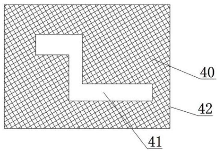
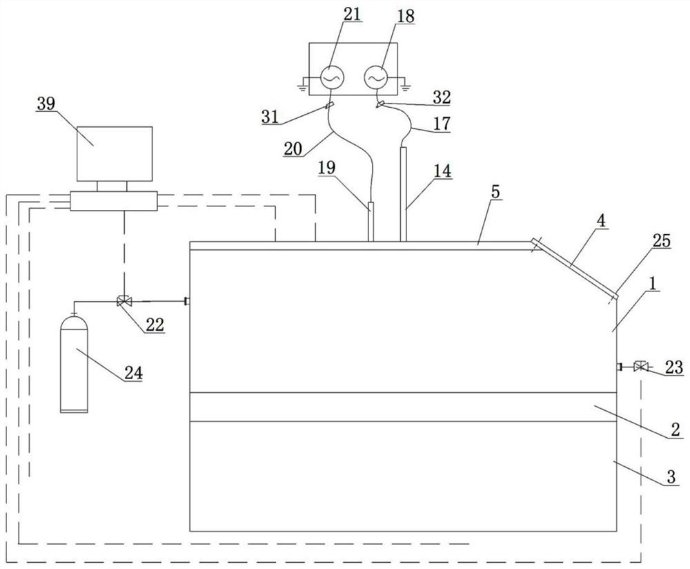
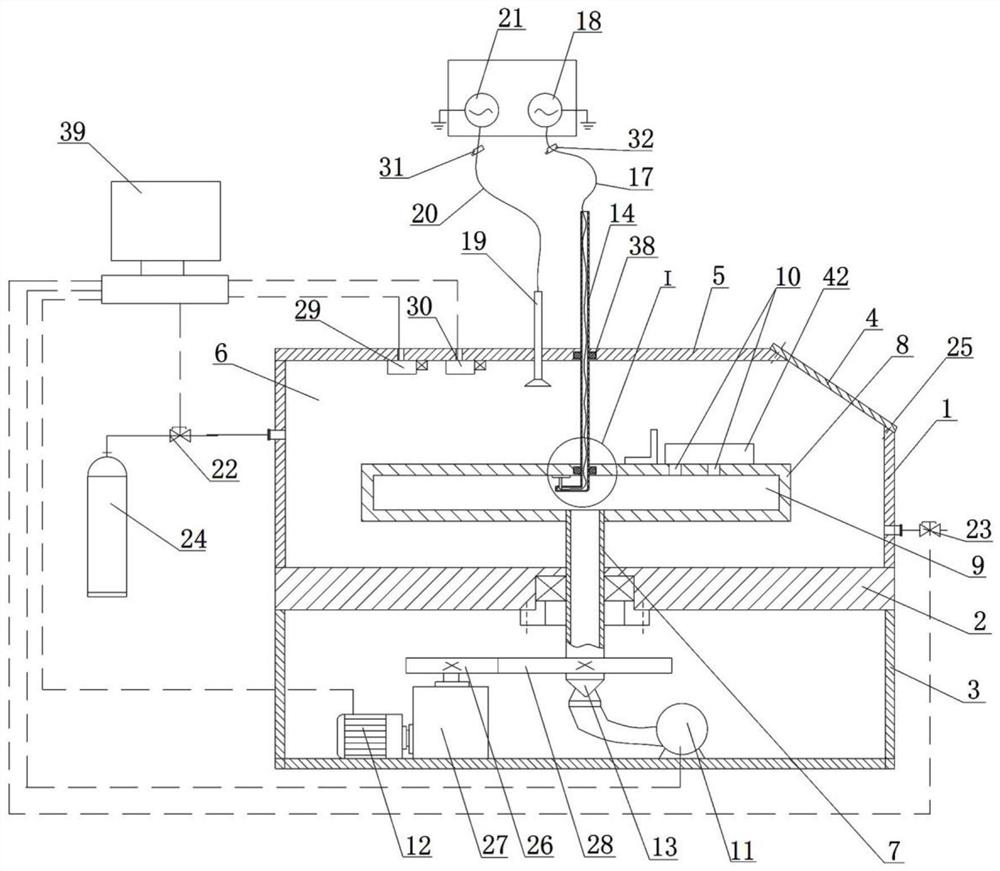
[0028] Embodiment one: if Figure 2-5 As shown, a plasma etching device for etching optical devices, it includes a casing 1, a workbench 2 and a chassis 3 arranged in sequence from top to bottom, the right end of the top of the casing 1 is provided with a gap, and the gap is provided with Airtight cover 4, airtight cover 4 is fixed between shell 1 and cover plate 5 through screw 25, and the top of described shell 1 is provided with cover plate 5, forms between shell 1, cover plate 5, airtight cover 4 and workbench 2 There is a closed cavity 6, and a hollow shaft 7 is installed in the workbench 2 through bearing rotation. The hollow shaft 7 is a plastic part. 8 is provided with a cavity 9, the cavity 9 communicates with the hollow shaft 7, a plurality of suction holes 10 are opened on the top surface of the suction cup 8 and on its edge, and the lower end of the hollow shaft 7 extends downwards in the cabinet 3, The cabinet 3 is provided with a vacuum pump 11 and a motor 12, t...

Embodiment 2

[0041] Embodiment two: if Figure 6~7 As shown, a plasma etching device for etching optical devices. The difference between this embodiment and Embodiment 1 is that an annular tube 33 is arranged in the sealed cavity 6, and the annular tube 33 is located outside the suction cup 8. The annular tube There are a plurality of small holes 34 on the inner ring of 33, and the small holes 34 communicate with the annular pipe 33, and the outer ring of the annular pipe 33 is welded with a branch pipe 35 communicating with the annular pipe 33. The branch pipe 35 runs through the shell 1 and extends to Outside the casing 1 , an air compressor 36 is connected to the extension end of the branch pipe 35 . A bracket 37 is welded to the bottom of the annular pipe 33 , and the bracket 37 is supported on the top surface of the workbench 2 .

[0042] The difference between the work process of this embodiment and embodiment one is:

[0043] After step S6 ends, the operator can turn on the air co...


PUM


Abstract

The invention discloses a plasma etching device for etching optical devices, which comprises a casing, a workbench and a cabinet arranged in sequence from top to bottom, a suction cup is welded on the top of the extension end of a hollow shaft, and a hollow shaft is connected between the output shaft of the motor and the hollow shaft. There is a transmission device that can drive the hollow shaft to rotate. The top of the horizontal tube is welded with an electrode column, and the upper end of the electrode column is welded with an electrode sheet. The electrode sheet contacts the inner wall of the top of the suction cup. The lower end of the electrode column extends into the horizontal tube and extends A wire B is fixed on the end, and the extension end of the wire B is connected to a second high-frequency power supply; the cover plate is provided with an antenna extending into the airtight cavity, the top of the antenna is connected to a wire A, and the other end of the wire A is connected to There is a first high-frequency power supply; the shell is provided with a solenoid valve and a pressure relief valve, and the other end of the solenoid valve is connected with a gas cylinder storing a gas source. The beneficial effect of the invention is that the etching efficiency is improved, the optical device cooling efficiency is improved, and the degree of automation is high.

Description

technical field [0001] The invention relates to the technical field of etching on optical devices, in particular to a plasma etching device for etching optical devices. Background technique [0002] Optical devices, including filters, lenses, polarizers, etc., are one of the indispensable and important components of electronic products. The surface of most optical devices is etched with grooves for installing circuits, wires or other small electronic components. To process the grooves, plasma etching equipment is usually used for etching. Adhesive protective film (40), to be etched part (41) exposed as figure 1 As shown, the optical device (42) is then put into the plasma etching device, and the plasma generated in the plasma etching device reacts with the part to be etched (41) to be removed, finally obtaining the groove of the desired shape . However, the existing plasma etching device has the following defects: 1. The optical device is thick, and it takes a long time t...

Claims


Application Information

Patent Timeline
Patent Type & Authority Patents(China)
IPC IPC(8): H01J37/02H01J37/08H01J37/147H01J37/20H01J37/305
CPCH01J37/3053H01J37/20H01J37/08H01J37/147H01J37/02
Inventor 朱巧芬刘秀红张雷席思星
Owner HEBEI UNIV OF ENG
Why Eureka
Try Eureka