


Quick Research
Generate reliable direction feasibility study reports for your R&D in just a few steps.

Technical Q&A
Discover and master advanced knowledge NOW. Basics, ideas, possibilities, all at once.

Find Solutions
As an expert in R&D theories, this can generate solutions to your technical problems instantly.

Evaluate Feasibility
Analyze your overall solution with one click, know your potential R&D risks in advance.

Monitor Landscape
Get weekly tech updates, stay abreast of the latest tech innovations and key insights.
Safe return route planning method for unmanned aerial vehicle
A return route and drone technology, applied in the field of drones, can solve the problems of inability to store in a large area and the inability to determine the elevation digital map, and achieve the effect of avoiding the risk of crashing.
- Summary
- Abstract
- Description
- Claims
- Application Information
AI Technical Summary
Problems solved by technology
Method used
Image


Examples
Embodiment 1
[0035] Such as figure 1 and figure 2 As shown, the UAV safe return route planning method of the present invention comprises the following steps:
[0036] a Establish a Cartesian coordinate system: Before the UAV takes off, plan the take-off point, route A, and route height on the PC terminal on the ground, take the plane where the route height is as the reference plane and take the orthographic projection of the take-off point on the plane where the route height is located Establish a Cartesian coordinate system for the origin P;
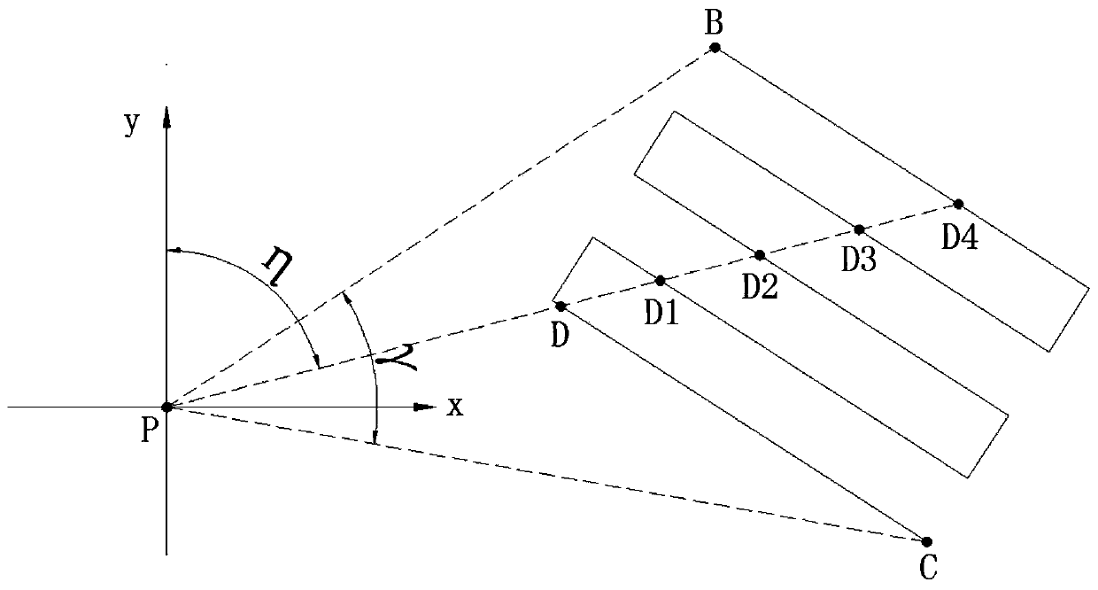
[0037] b Determine the azimuth angle of the route: make an azimuth γ in the rectangular coordinate system to ensure that the route A is within the range of the azimuth angle, and the two sides of the azimuth γ form two angles (α, β) with the positive direction of the y-axis , α<β;
[0038] c Find the elevation digital map in the azimuth angle range: select an angle increment δ, the angle increment δ is: 0.5 °; take α as the starting angle, increa...
Embodiment 2
[0043] Such as figure 1 , figure 2 and image 3 As shown, this embodiment is a further improvement made on the basis of Embodiment 1. In the step b, the two sides of the azimuth γ are tangent to the route, the α is the minimum azimuth, and the minimum azimuth is the minimum angle between the point on the route and the line connecting the origin P and the positive y-axis; the β is the maximum azimuth angle, and the maximum azimuth is the point on the route A and the origin P connecting the line and the y-axis The positive included angle is the angle of the maximum angle.
[0044] working principle: figure 1 and figure 2 It shows a situation where the minimum azimuth α is the angle between the line connecting the origin P and the starting point of the route B and the positive direction of the y-axis; the maximum azimuth β is the angle between the line connecting the origin P and the end point C of the route and the positive direction of the y-axis ;
[0045] image 3 ...
Embodiment 3
[0048] This embodiment is a further improvement made on the basis of Embodiment 1. In the step c, the intersection point between the direction vector of the angle increment δ and the route A is the farthest intersection point of the route A away from the origin P.
[0049] Working principle: as figure 2 As shown, the route is a curved path back and forth. When the angle is η, there are 5 intersection points (D, D1, D2, D3, D4) between the direction vector of this angle and the route, in order to ensure that the elevation digital map in the route can be fully detected , so choose the intersection point D4 farthest from the take-off point.
PUM
 Abstract
Description
Claims
Application Information
 - R&D Engineer
- R&D Manager
- IP Professional
- Industry Leading Data Capabilities
- Powerful AI technology
- Patent DNA Extraction
Browse by: Latest US Patents, China's latest patents, Technical Efficacy Thesaurus, Application Domain, Technology Topic, Popular Technical Reports.
© 2024 PatSnap. All rights reserved.Legal|Privacy policy|Modern Slavery Act Transparency Statement|Sitemap|About US| Contact US: help@patsnap.com