
Water seepage device and method

A technology of seepage pipes and seepage holes, which is applied to water supply devices, sewage discharge, waterway systems, etc., can solve the problems of inability to play the role of permeable concrete, high cost, and short service time, so as to alleviate urban waterlogging disasters, simple construction, and low cost cheap effect

Pending Publication Date: 2020-03-06
辛振科
View PDF0 Cites 6 Cited by
  • Summary
  • Abstract
  • Description
  • Claims
  • Application Information

AI Technical Summary

Problems solved by technology

[0003] The current permeable concrete has low strength, short service time, complicated preparation process, high cost, easy clogging of water seepage pores, and water seepage holes (chambers) cannot fully guarantee Unicom
In order to solve the problem that the service time of permeable concrete is too short, some permeable concrete ground projects lay a layer of conventional concrete under the permeable concrete, which cannot play the role of permeable concrete at all.
In some permeable brick paving projects, a layer of conventional concrete is first laid, and then a layer of fine sand is laid on the conventional concrete, and then permeable bricks are laid on the fine sand layer, which also fails to play the role of permeable bricks.

Method used


Image

  • Water seepage device and method
  • Water seepage device and method
  • Water seepage device and method

Examples


Embodiment 1

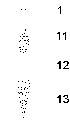
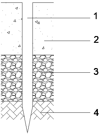
[0016] Such as figure 1 and figure 2 As shown, a water seepage device and method, including a water seepage device 1, the water seepage device 1 is placed in the (asphalt) concrete ground structure, and the (asphalt) concrete ground structure is soil foundation 4 and coarse sand cushion from bottom to top 3 and (asphalt) concrete layer 2. The upper part of the water seepage device 1 is flush with the upper surface of the (asphalt) concrete layer 2 , and the water seepage device 1 is composed of a water seepage material 11 , a water seepage pipe 12 and a water seepage hole 13 . The seepage material 11 is installed in the seepage pipe 12, one end of the seepage pipe 12 extends into the soil foundation 4 to a certain depth, and the part of the seepage pipe 12 extending into the soil foundation 4 has a water seepage hole 13, and the seepage pipe 12 extends into the soil foundation 4. One end of the foundation 4 is conical, and the water seepage material 11 is preferably fine-gr...

Embodiment 2

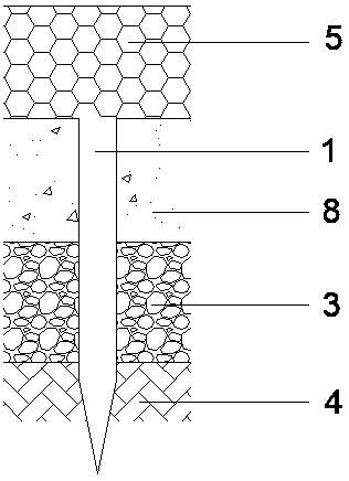
[0018] This embodiment is the application of this method in the permeable concrete ground structure, specific reference image 3 , The permeable concrete ground structure is the soil foundation 4, the coarse sand cushion 3, the concrete cushion 8 and the permeable concrete layer 5 from bottom to top. The water seepage device 1 passes through the concrete cushion 8, the upper part of the water seepage device 1 is flush with the upper surface of the concrete cushion 8 and the lower surface of the permeable concrete layer 5, and the lower part of the water seepage device 1 extends into the soil foundation 4 to a certain depth . The water seepage device 1 can be replaced by water permeable materials such as small stakes and straw ropes.

Embodiment 3

[0020] This embodiment is the application of this method in the permeable brick paved ground structure, specifically refer to Figure 4 , The permeable brick paving ground structure from bottom to top is soil foundation 4, coarse sand cushion 3, concrete cushion 8, fine sand cushion 7, and permeable brick layer 6. The water seepage device 1 passes through the concrete cushion 8 , the upper part of the water seepage device 1 is flush with the upper surface of the concrete cushion 8 and the lower surface of the fine sand cushion 7 , and the lower part of the water seepage device 1 extends into the soil foundation 4 . The water seepage device 1 can be replaced by water permeable materials such as small stakes and straw ropes.


PUM


Abstract

The invention discloses a water seepage device and method. The water seepage device and method comprise a water seepage device, and the water seepage device is arranged in a ground structure. The lower end of the water seepage device is in a conical shape and extends into a soil base, the part, extending into the soil base, of the water seepage device is provided with water seepage holes, the water seepage device penetrates through a waterproof concrete layer, and a channel is formed between the soil base and ground surface gathered water. The water seepage device comprises a water seepage pipe, a water seepage material and the water seepage holes, and the water seepage device can be replaced by a straw rope, a small wood pile and other water seepage materials. The water seepage device andmethod is simple in structure, easy and convenient to construct, low in cost and capable of effectively seeping into urban ground rainwater, and has certain reference significance in relieving urbanwaterlogging and building a sponge city.

Description

technical field [0001] The invention belongs to the technical field of rainwater infiltration, in particular to a water infiltration device and method. Background technique [0002] With the development of urbanization, the problem of urban waterlogging is becoming more and more serious. By comparing the city and the countryside, we can find that there are a lot of urban construction land, and most of the non-construction land is hardened by cement and asphalt for the cleanness and tidiness of the urban ground environment. caused flooding. [0003] The current permeable concrete has low strength, short service life, complex preparation process, high cost, easy blockage of water seepage pores, and the inability of water seepage holes (chambers) to fully guarantee connectivity. In order to solve the problem that the service time of pervious concrete is too short, some pervious concrete ground projects lay a layer of conventional concrete under the pervious concrete, which ca...

Claims


Application Information

Patent Timeline
IPC IPC(8): E01C5/04E01C11/22E03F1/00
CPCE01C5/04E01C11/225E03F1/002Y02A10/30Y02A20/40
Inventor 辛振科刘立朋杨泓周栖苏盼珠李秀红秦洲吕康玄王建海王建平杨生青覃艳奎马俊庭安得海张义发何万梅
Owner 辛振科
Learn More