
Rotor screen preparing device

A technology for preparing device and screen mesh, applied in the field of stainless steel rotor screen mesh preparation device, can solve the problems of large dust flying, large centrifugal speed and gas vorticity, easy deformation, etc. The effect of high production efficiency

Active Publication Date: 2020-03-06
NINGBO INST OF MATERIALS TECH & ENG CHINESE ACADEMY OF SCI
View PDF10 Cites 2 Cited by
  • Summary
  • Abstract
  • Description
  • Claims
  • Application Information

AI Technical Summary

Problems solved by technology

[0005] In the usual pulverizer, due to the large centrifugal speed and large air vortex, it is difficult to collect the powder during the pulverization process, and in the production process, the dust is flying and the waste is large. Therefore, it is very difficult for pharmaceutical manufacturers to produce freeze-dried powder injections. Use less of this process
The aperture and mesh of the rotor screen of the conventional rapid granulator are not less than 1.5mm, and the wall thickness of the sieve is not less than 1.2mm, which cannot meet the crushing requirements of the freeze-dried powder injection. Therefore, the rotor screen of the conventional rapid granulator Can not be used in whole grain crushing of freeze-dried powder injection
[0006] Due to the special structure of the rotor screen used in the fast granulator, it is difficult to make the wall thickness of the screen less than 1.5mm in the existing technology, otherwise it is easy to deform during welding, making the rotor screen rotate Time concentricity cannot be guaranteed
[0007] At present, there is a lack of an economical, efficient and reliable small-aperture and fine-mesh rotor screen preparation device in the market, so there is an urgent need to study a new rotor screen preparation device, which has considerable significance for improving the application range of the fast granulator

Method used


Image

  • Rotor screen preparing device
  • Rotor screen preparing device
  • Rotor screen preparing device

Examples


Embodiment Construction

[0037] In the following, the present invention will be further described in detail according to the accompanying drawings and specific embodiments.

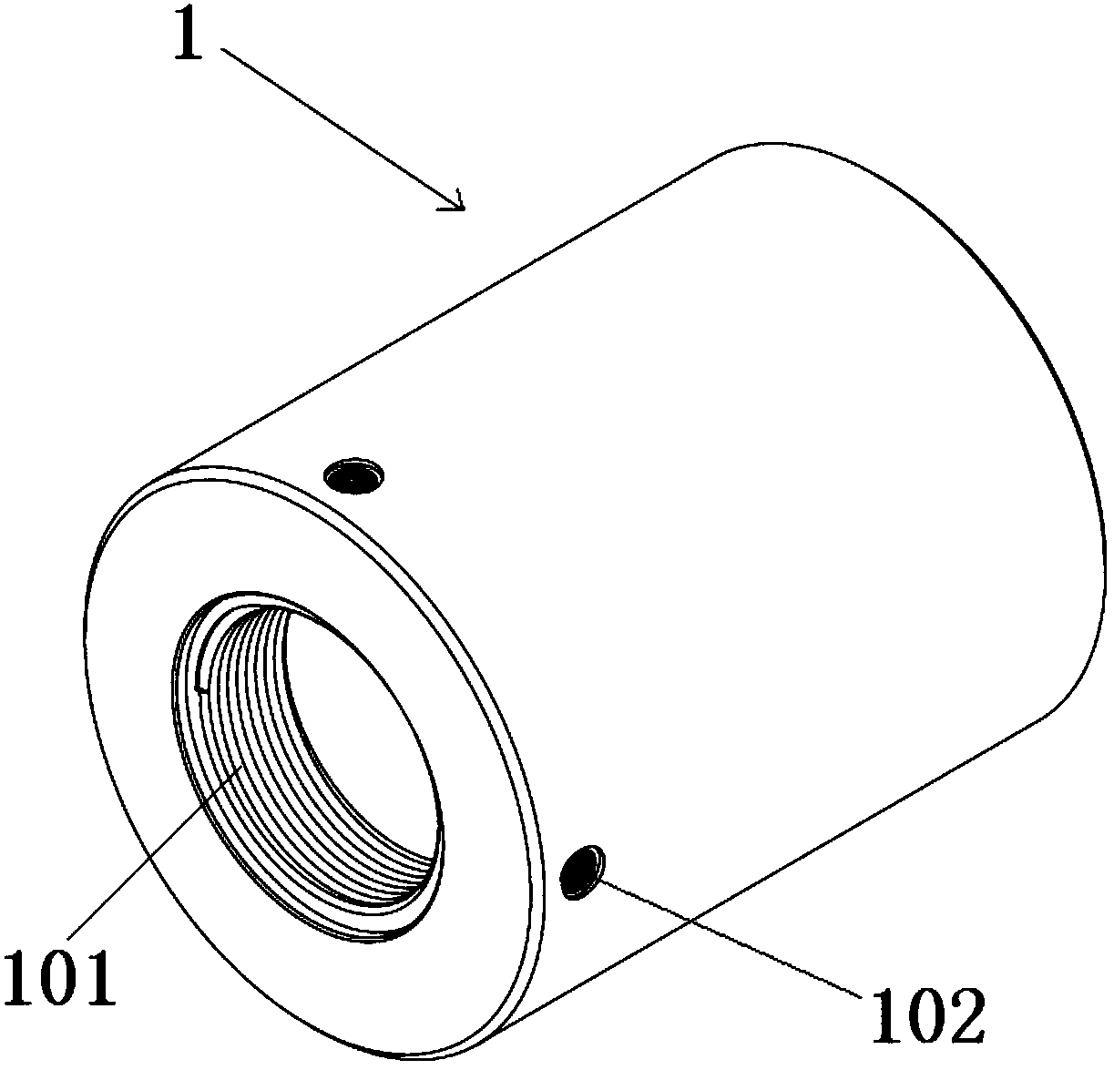
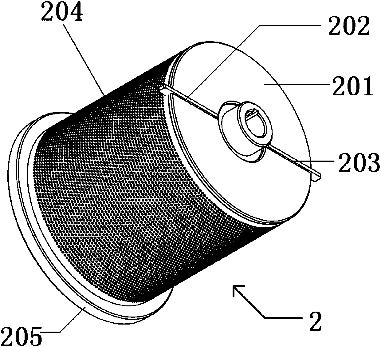
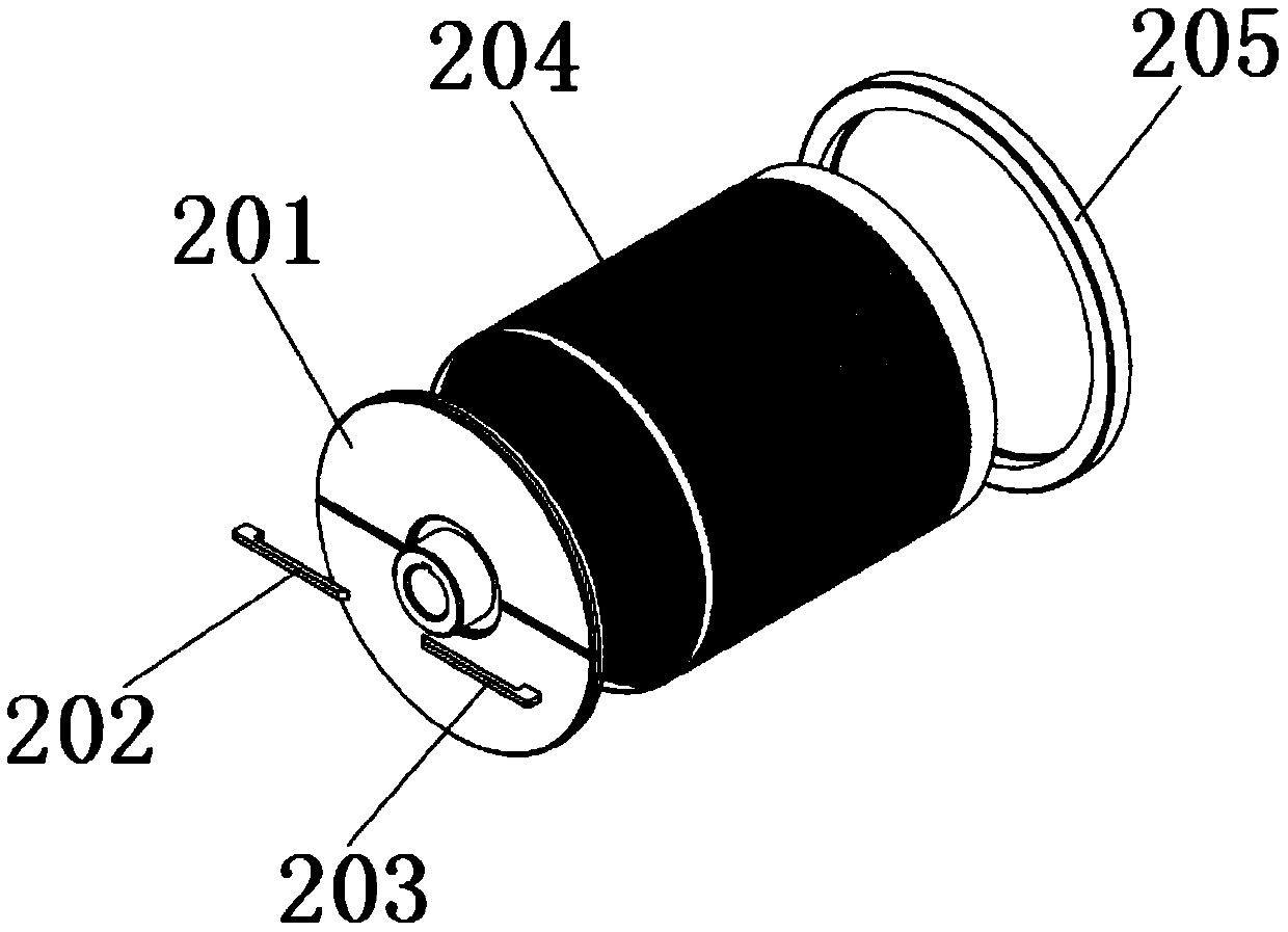
[0038] Such as Figure 1-9 As shown, a rotor screen preparation device includes a positioning mandrel 1, a rotor screen assembly 2, a welding locking mechanism 3, a lathe spindle chuck 4, a lathe spindle box 5, a four-jaw chuck device 6, a pull-out Die mechanism7.

[0039] Such as figure 1 As shown, the positioning mandrel 1 of this embodiment is cast from ductile iron, the hollow structure has a wall thickness of 10 mm, an outer diameter of 200 mm, a fit tolerance of H7 level is preferred, and a length of 250 mm. Large threaded holes 101 and Small threaded holes, among them, there is a stepped positioning hole at 101 of the large threaded hole to match the lathe spindle chuck. The diameter of the stepped hole is 116mm, and the fit tolerance is preferably H7. The depth of the stepped hole is 5mm. There are 4 threads arranged ar...


PUM


Abstract

The invention discloses a rotor screen preparing device. The rotor screen preparing device comprises a positioning core mold, a welding locking mechanism, a turning mechanism, a pulling-out demouldingmechanism, and a clamping device, wherein the positioning core mold is used for being sleeved with a rotor screen assembly, and the rotor screen assembly is composed of a rotary disc flange, left andright scraper plates, a screen body and a screen upper flange; the welding locking mechanism is used for locking the positioning core mold and the rotor screen assembly before welding; the turning mechanism is used for turning the rotor screen assembly after welding; the pulling-out demoulding mechanism is used for separating and demoulding the rotor screen assembly and the positioning core moldafter turning; and the clamping device is used for fixing the rotor screen assembly during separating and demoulding, the positioning core mold is of a hollow structure, a large thread hole and a small thread hole are formed in the two end surfaces of the positioning core mold correspondingly, and a step positioning hole matched with a spindle chuck of the turning processing mechanism is formed inthe large thread hole. By means of the rotor screen preparing device, the machining accuracy can be improved, the number of the holes and is increased, the hole diameter is reduced, the mesh number of a rotor screen is increased, and the crushed whole particles are finer accordingly.

Description

technical field [0001] The invention belongs to the technical field of dry granulation process of medicines, and in particular relates to a stainless steel rotor screen preparation device. Background technique [0002] The fast granulation machine is mainly suitable for the granulation of non-uniform dry granules in the pharmaceutical, chemical, food and other industries. The granules after granulation are uniform in size, which is suitable for tablet compression and capsule filling. [0003] The principle of the granulator is that the rotating rotor screen rotates and stirs the raw materials in the working cylinder, and throws the particles to the screen surface by centrifugal force. Between the knife holder and the screen, it is crushed into small particles and discharged through the screen holes. The size of the crushed particles is adjusted by the mesh number of the screen, the distance between the stator knife holder and the screen, and the speed of the rotor screen. ...

Claims


Application Information

Patent Timeline
IPC IPC(8): B23P15/00B07B1/46
CPCB07B1/4618B23P15/00
Inventor 冯雄峰范逸闻祝颖丹
Owner NINGBO INST OF MATERIALS TECH & ENG CHINESE ACADEMY OF SCI
Learn More