
Method for improving spot-welding quality of laser spot-welded duct plate

A solder joint quality, laser spot welding technology, applied in laser welding equipment, welding equipment, welding equipment and other directions, can solve problems such as breakdown of air duct plates, scrapping, affecting the strength and apparent quality of solder joints, etc., to improve quality Effect

Inactive Publication Date: 2020-03-06
上海电气集团上海电机厂有限公司
View PDF11 Cites 0 Cited by
  • Summary
  • Abstract
  • Description
  • Claims
  • Application Information

AI Technical Summary

Problems solved by technology

Due to the influence of equipment accuracy, positioning accuracy of tooling and straightness accuracy of welded flat steel, some solder joints are affected by offset center, poor contact and other reasons, which will affect the strength and appearance quality of solder joints, and even have large offset The risk of scrapping due to breakdown of the air duct plate

Method used


Image

  • Method for improving spot-welding quality of laser spot-welded duct plate

Examples


Embodiment Construction

[0016] In order to better understand the technical solution of the present invention, the following will be described in detail through specific examples:

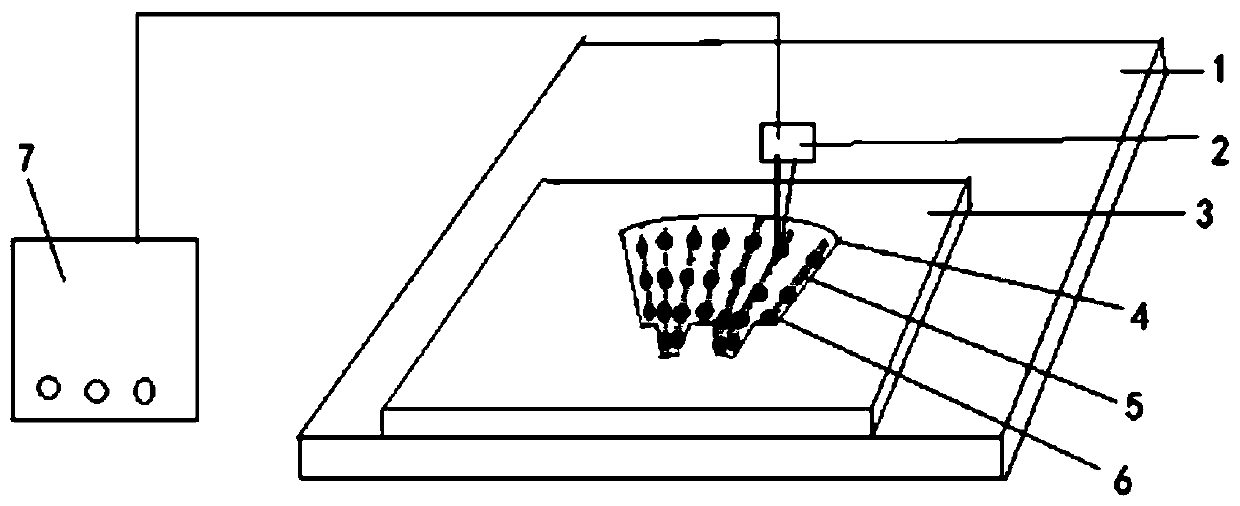
[0017] see figure 1 , a method for improving the quality of laser spot welding air duct plate solder joints of the present invention is used for welding on the surface of the air duct plate, and is characterized in that it comprises the following steps:

[0018] In step 1, the positioning tool 3 is hoisted to the workbench 1, and then the positioning tool 3 is fixed by positioning pins.

[0019] Step 2, place the workbench 1 at the limit position of the corner of the work area, so that it is easy to locate and difficult to cause relative displacement. Since it is necessary to inspect the solder joints of the sample after the trial run, the determined limit position can ensure that the position of the workbench 1 is consistent before and after the inspection and does not deviate.

[0020] Step 3. Divide all the air ducts ...


PUM


Abstract

The invention discloses a method for improving the spot-welding quality of a laser spot-welded duct plate. The method comprises the steps that before formal mass laser welding is conducted according to normal welding parameters, test welding is conducted by means of low-power laser parameters according to a written laser welding spot position program to form pits in the surface of a duct piece, and then the laser welding spot position program is adjusted according to the positions of the pits until it is determined by visual inspection that all pits are located at the center of a preset welding spot. By the adoption of the method for improving the spot-welding quality of the laser spot-welded duct plate, the control precision of welding spots is guaranteed, and the quality of laser weldingis improved.

Description

technical field [0001] The invention relates to a method for improving the quality of laser spot welding air duct plate welding points used in the field of laser welding. Background technique [0002] The current laser welding process generally compiles the welding program according to the laser welding position marked on the drawing, and then sends the air duct plate into the work area after being positioned by the tooling, enters the welding parameters (welding parameters that have been evaluated by the process), and starts the welding program. Laser welding of the established route. Due to the influence of equipment accuracy, tooling positioning accuracy, and straightness accuracy of welded flat steel, some solder joints are affected by offset center and poor contact, which will affect the strength and appearance quality of solder joints, and even have large offsets. Breaking through the air duct plate creates a risk of scrapping. Contents of the invention [0003] Th...

Claims


Application Information

Patent Timeline
IPC IPC(8): B23K26/22B23K37/04
CPCB23K26/22B23K37/04
Inventor 唐群花
Owner 上海电气集团上海电机厂有限公司
Learn More