
Connecting rod floating ball liquid level switch

A floating ball liquid level and connecting rod technology, which is applied in the direction of robot floating motion actuation, can solve the problems of the influence of the service life of the magnetic reed switch, the continuous switching of the magnetic reed switch, and the accumulation of a lot of dirt on the floating ball. Avoid continuous closure, increase service life, and reduce the accumulation of dirt

Inactive Publication Date: 2020-02-28
东台市高科技术创业园有限公司
View PDF3 Cites 6 Cited by
  • Summary
  • Abstract
  • Description
  • Claims
  • Application Information

AI Technical Summary

Problems solved by technology

[0003] The connecting rod float level switch can monitor and detect the liquid level, but in actual use, it is impossible to always place the switch on a completely still liquid for detection. Many liquids are flowing, so when using the connecting rod When the float level switch is on, the flowing liquid will constantly exert a force on the float, causing the float to rise up and down continuously, and the upper and lower limits of the float itself are very close, so it will cause magnetic The continuous on and off of the reed switch not only has a great impact on the service life of the reed switch, but also triggers the alarm continuously, which is very troublesome for normal production, and it is difficult to achieve stable detection, real-time and accurate liquid level
[0004] The connecting rod float level switch uses a ring magnet to control the orpiment switch, but most of the time it is below the alarm water level, so the ring magnet actually does not work in many cases, but it will also absorb liquid due to magnetic force A lot of solid particles in the floating ball will cause a lot of dirt to accumulate on the inner wall of the floating ball, which needs to be cleaned frequently, which consumes a lot of manpower and material resources

Method used


Image

  • Connecting rod floating ball liquid level switch
  • Connecting rod floating ball liquid level switch
  • Connecting rod floating ball liquid level switch

Examples


Embodiment Construction

[0024] The following will clearly and completely describe the technical solutions in the embodiments of the present invention with reference to the accompanying drawings in the embodiments of the present invention. Obviously, the described embodiments are only some of the embodiments of the present invention, not all of them. Based on the embodiments of the present invention, all other embodiments obtained by persons of ordinary skill in the art without making creative efforts belong to the protection scope of the present invention.

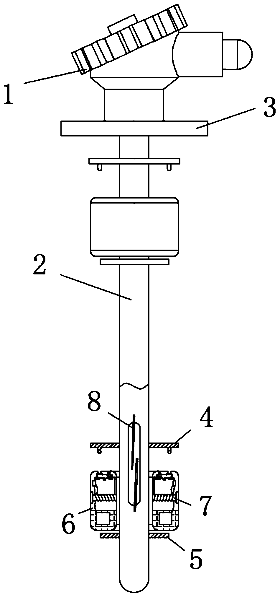
[0025] see Figure 1-4 , a connecting rod float liquid level switch, including a top cover 1, the bottom of the top cover 1 is fixedly connected to a connecting rod 2, the top of the connecting rod 2 is fixedly provided with a mounting flange 3, and the outer side of the connecting rod 2 is movable socketed with a floating The ball 6 and the floating ball 6 can slide between the upper limit ring 4 and the lower limit ring 5 of the connecting rod ...


PUM


Abstract

The invention relates to the technical field of electronic devices, and discloses a connecting rod floating ball liquid level switch. The connecting rod floating ball liquid level switch comprises a top cover, wherein the bottom of the top cover is fixedly connected with a connecting rod, the top of the connecting rod is fixedly provided with a mounting flange, the outer side of the connecting rodis movably sleeved with a floating ball body, the floating ball body can slide between an upper limiting ring and a lower limiting ring of the connecting rod, a magnetic reed switch is fixedly mounted in the connecting rod, an electromagnet is mounted in the floating ball body, the top of the upper limiting ring is provided with a protruding head, the top of the lower limiting ring is provided with a groove, the electromagnet is connected with an on-off device and a battery through wires, one side of the top of the on-off device is fixed with a spring, and the floating ball body is provided with a limiting block at the bottom of the on-off device. The connecting rod floating ball liquid level switch can effectively prevent the influence of water waves on the switch, and is slow in accumulation of dirt.

Description

technical field [0001] The invention relates to the technical field of electronic devices, in particular to a connecting rod float liquid level switch. Background technique [0002] When using and storing liquid, it is often necessary to control the amount of liquid in real time. Generally, a connecting rod float level switch is used to control the amount of liquid to prevent it from overflowing due to excessive storage. The working principle of the float level switch: By setting a ring magnet in the float, the float will rise under the action of buoyancy. When it rises to the alarm height, the magnet in the float will meet the magnetic spring inside the connecting rod. The switch generates a magnetic force, which makes the magnetic reed switch turn on, and the connected circuit will transmit a signal to inform that the water level of the liquid has reached a dangerous position and needs to be treated. When the water level drops, the float ball will fall, and the magnetic re...

Claims


Application Information

Patent Timeline
IPC IPC(8): H01H36/02
CPCH01H36/02
Inventor 俞快
Owner 东台市高科技术创业园有限公司
Learn More