
Control device and method for landing point area and speed of deep sea lander

A control device and lander technology, applied in height or depth control, vehicle position/route/height control, instruments, etc., can solve the problem of lack of speed control and the ability to resist ocean currents, the influence of underwater operation of the device, and unretrieved problems etc. to reduce the landing speed, consume less energy, and reduce the impact

Pending Publication Date: 2020-02-28
SHANDONG UNIV +1
View PDF0 Cites 3 Cited by
  • Summary
  • Abstract
  • Description
  • Claims
  • Application Information

AI Technical Summary

Problems solved by technology

[0003] Existing deep-sea landers rely on gravity and buoyancy to achieve submersion and floating. They do not have the ability to control speed and resist ocean currents. They are greatly affected by ocean currents. The lander lacks the active control function of movement and landing point, and it is difficult to land within the predetermined target range.
In addition, if the landing speed of the lander is too high, it will affect the device itself and underwater operations
However, no related schemes have been retrieved for the control of the landing area and the deceleration before landing for the self-elevating deep-sea lander

Method used


Image

  • Control device and method for landing point area and speed of deep sea lander
  • Control device and method for landing point area and speed of deep sea lander
  • Control device and method for landing point area and speed of deep sea lander

Examples


Embodiment Construction

[0045] In order to clearly illustrate the technical features of this solution, the present invention will be described in detail below through specific implementation modes and in conjunction with the accompanying drawings.

[0046] It should be noted that many specific details are set forth in the following description to facilitate a full understanding of the present invention, however, the present invention can also be implemented in other ways than those described here. Therefore, the protection scope of the present invention is not limited by the specific embodiments disclosed below.

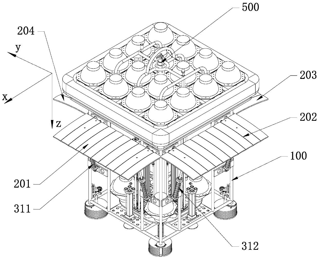
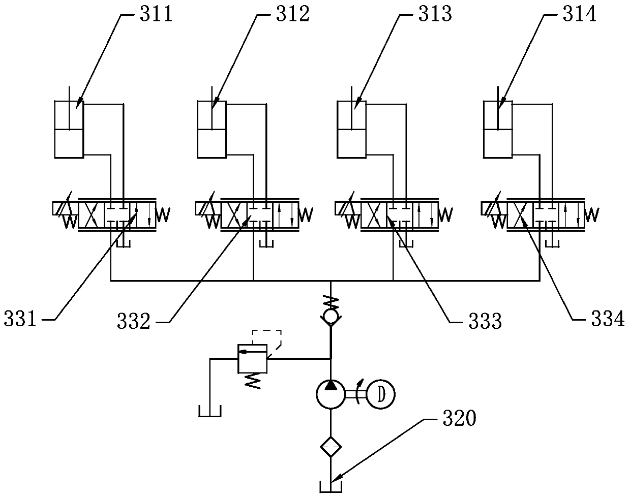
[0047] Such as figure 1As shown in , the control device for the landing area and speed of the deep-sea lander provided by the present invention includes a carrying platform 100. Specifically, in order to reduce the overall weight of the lander and facilitate the installation of required equipment, the carrying platform 100 is designed as The main body of the rectangular frame, and the floa...


PUM


Abstract

The invention discloses a control device and method for the landing point area and the speed of a deep-sea lander. The device comprises a carrying platform, wing plates, a hydraulic system, an attitude sensor, an underwater sound communication machine and a control unit. The method comprises the steps of first, building a fixed coordinate system O2-xyz; second, building a follow-up coordinate system O1-xyz on the carrying platform; third, calculating a coordinate value of the center of the carrying platform in the fixed coordinate system; fourth, calculating a coordinate value of the central point of the landing area in the follow-up coordinate system, and marking the direction nt of a connection line from the central point of the landing area to the central point of the carrying platform;and fifth, enabling the direction of the resultant force of the thrust of one wing plate and the thrust of the other wing plate to be the same as the direction nt. According to the control device andmethod for the landing point area and the speed of the deep-sea lander, after the lander is affected by sea current in the diving process, adjustment can be carried out with the control method to make the lander get close to a target area continuously, the accuracy and energy consumption of landing can be adjusted by changing the control interval time delta t, and it is guaranteed that the landing point is within the expected detection area range.

Description

technical field [0001] The invention relates to a control device and method for the landing area and speed of a deep-sea lander, belonging to the field of marine detection equipment. Background technique [0002] The scope of human development and exploration of the ocean is becoming wider and wider. In the field of deep-sea exploration, the autonomous heave deep-sea lander provides effective technical support for exploring frontier scientific issues in the deep sea due to its low cost and high flexibility. [0003] Existing deep-sea landers rely on gravity and buoyancy to achieve submersion and floating. They do not have the ability to control speed and resist ocean currents. They are greatly affected by ocean currents. The lander lacks the active control function of movement and landing point, and it is difficult to land within the predetermined target range. . In addition, if the landing speed of the lander is too high, it will affect the device itself and underwater op...

Claims


Application Information

Patent Timeline
IPC IPC(8): B63C11/52G05D1/06
CPCG05D1/0692B63C11/52
Inventor 刘延俊薛祎凡薛钢
Owner SHANDONG UNIV
Learn More