Joint mounting equipment and connecting method of flexible pipe and joint

A technology for installing equipment and flexible pipes, which is applied in the field of fixtures and fixtures, can solve the problems of affecting the safety of operators, unguaranteed quality, and low pressing efficiency, and achieve the effects of simple and convenient operation, reducing the number of operators, and high pressing efficiency

Active Publication Date: 2020-02-28
SHENGLI OIL FIELD XINDA PIPE IND TECH DEV CO LTD
View PDF8 Cites 4 Cited by
  • Summary
  • Abstract
  • Description
  • Claims
  • Application Information

AI Technical Summary

Problems solved by technology

[0004] In view of the deficiencies in the prior art described above, the purpose of the present invention is to provide an auxiliary device for installation of flexible pipes and joints, so as to solve the problems in the prior art that the installation of flexible pipe joints relies on manual operation for low efficiency and high quality. If there is no guarantee, it is easy to affect the technical problems of the operator's safety

Method used


Image

  • Joint mounting equipment and connecting method of flexible pipe and joint
  • Joint mounting equipment and connecting method of flexible pipe and joint
  • Joint mounting equipment and connecting method of flexible pipe and joint

Examples


Embodiment

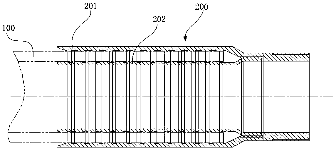
[0048] figure 1 Shown is a schematic diagram of the connection between the flexible pipe and the joint. The joint 200 has an inner pipe 202 and an outer pipe 201. The first end of the inner pipe 202 and the first end of the outer pipe 201 are connected correspondingly, such as threaded connection, etc. The flexible pipe 100 is connected from the joint. The second end of 200 is inserted between the inner tube 202 and the outer tube 201 .

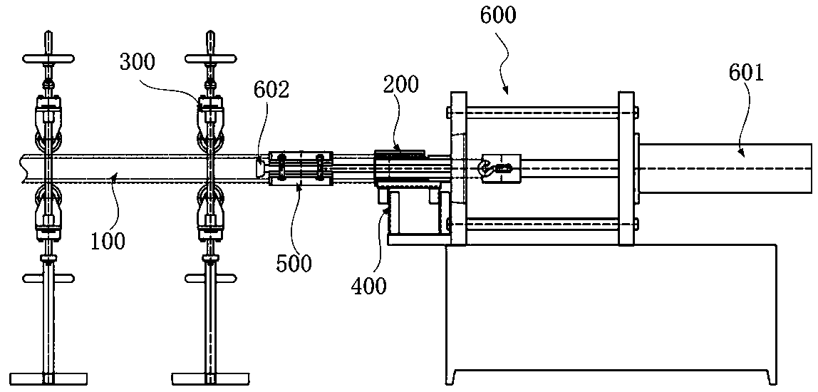
[0049] Such as figure 2 As shown, a joint installation device illustrated in this example is used for the auxiliary connection of the end of the flexible pipe 100 and the joint 200, wherein the joint 200 includes an inner tube 202 and an outer tube 201 whose ends are connected, and the inner tube 202 is connected to the outer tube 200. The tube 201 forms an annular cavity for accommodating the end of the flexible tube 100. The end of the flexible tube 100 is inserted into the annular cavity to be connected with the joint 200 and pressed tig...


PUM


Abstract

The invention provides joint mounting equipment and a connecting method of a flexible pipe and a joint. The joint mounting equipment comprises a joint supporting mechanism for placing a joint, a pipemounting dragging mechanism and a joint pressing mechanism, wherein the joint supporting mechanism is used for supporting the flexible pipe and aligning the flexible pipe and a flexible pipe aligned to the joint to a bracket; the pipe mounting dragging mechanism is sleeved on the flexible pipe for pulling the flexible pipe to move toward the joint and inserting the flexible pipe into the joint; and the joint pressing mechanism is used for compacting the flexible pipe and the joint and comprises a joint outer pressing die, a joint inner swelling die, a baffle plate and a driving mechanism. Whenthe joint is pressed, the driving mechanism enables the joint inner swelling die and the joint to move relatively along the axial direction of the joint and the joint outer pressing die and the jointto move relatively along the axial direction of the joint; and the baffle plate is used for limiting axial movement of the joint when the flexible pipe is inserted into the joint. The joint mountingequipment is high in pressing efficiency, the quantity of operators for mounting the joint of the flexible pipe is reduced greatly, and meanwhile, the risk of mounting the joint of the flexible pipe is reduced, the mounting precision and the pressing efficiency are improved greatly, and the safety is improved.

Description

technical field [0001] The invention belongs to the technical field of fixtures, and in particular relates to a joint installation device and a connection method between a flexible pipe and a joint. Background technique [0002] At present, in the flexible pipe production process, it is necessary to install joints at both ends of the flexible pipe to realize the connection of multi-section flexible pipes. The flexible pipe is wound on the reel. The weight and size of the flexible pipe roll are relatively large, and the joint pressing position has a certain height. , When installing, it is necessary to raise one end of the flexible pipe installation joint to the joint pressing position. [0003] In the prior art, the joint pressing is realized by hydraulic equipment. The support of the joint, the insertion of the flexible pipe into the joint, and the lifting of one end of the flexible pipe to press the joint to the joint pressing position are usually performed manually and re...

Claims


Application Information

Patent Timeline
Patent Type & Authority Applications(China)
IPC IPC(8): B29C65/56B29C65/78B29L23/00
CPCB29C65/56B29C65/7814B29C65/7838B29C65/7858B29C66/49B29C66/53241B29C66/5344B29C66/61B29L2023/005
Inventor 朱华许兆宁李仁闯王学鹏
Owner SHENGLI OIL FIELD XINDA PIPE IND TECH DEV CO LTD
Why Eureka
Try Eureka