Pressure limiting valve assembly and cooking utensil

A technology of cooking utensils and pressure limiting valves, which is applied in the field of pressure limiting valve components and cooking utensils, can solve the problems of poor sealing, overflow of soup in the pressure cooker, waste of energy, etc., and achieve the effect of long service life

Pending Publication Date: 2020-02-28
绍兴市吉柏尼机电有限公司
View PDF0 Cites 5 Cited by
  • Summary
  • Abstract
  • Description
  • Claims
  • Application Information

AI Technical Summary

Problems solved by technology

It generally takes a long time from the leakage of the pressure limiting valve to the pressure stabilization, and some pressure limiting valves with poor sealing will take longer to reach the pressure balance
In this way, not only is energy wasted, but also the soup in the pressure cooker will easily overflow due to long-term exhaust
In addition, the food that requires high pressure cooking will affect the cooking effect because there is no instantaneous high pressure

Method used


Image

  • Pressure limiting valve assembly and cooking utensil
  • Pressure limiting valve assembly and cooking utensil
  • Pressure limiting valve assembly and cooking utensil

Examples


Embodiment 1

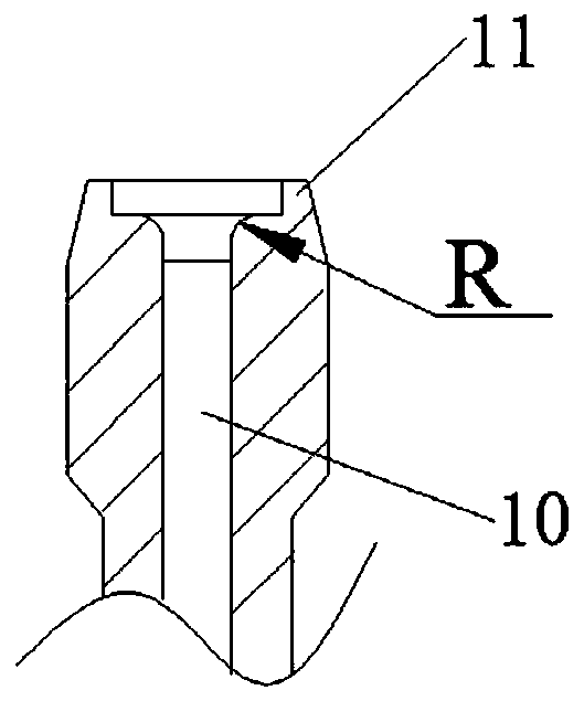
[0029] like figure 1 As shown, the pressure limiting valve assembly of this embodiment includes an exhaust pipe 1 and a pressure limiting valve 2, and the pressure limiting valve 2 is installed on the exhaust pipe 1.

[0030] Specifically, such as figure 1 As shown, the pressure limiting valve 2 includes a valve body 21 and a spherical valve core 22 , and the spherical valve core 22 is connected to the inner chamber of the valve body 21 through a connecting piece 23 . Wherein, the connecting piece 23 and the spherical valve core 22 can be connected through a necking structure, and the necking refers to a forming process of shrinking the mouth of a preformed cylinder or pipe blank through a necking die. In addition, the connection method between the connecting piece 23 and the spherical valve core 22 can also refer to the connection method in the prior art, such as welding, crimping, overmolding or integral molding, which will not be repeated here.

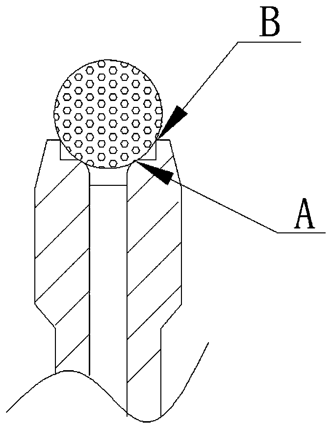
[0031] like figure 2 As...

Embodiment 2

[0041] The difference between the pressure limiting valve assembly of this embodiment and Embodiment 1 is:

[0042] The inner wall of the first step is chamfered, and the chamfered surface intersects with the spherical surface of the spherical valve core to form a line to form the first sealing structure; other structures can refer to Embodiment 1.

[0043] In the cooking appliance of this embodiment, the pressure limiting valve assembly it includes is the pressure limiting valve assembly of this embodiment; other structures can refer to Embodiment 1.

[0044] The pressure-limiting valve assembly and the cooking utensil of this embodiment can also realize the breathing exhaust effect and realize structural diversification.

Embodiment 3

[0046] The difference between the pressure limiting valve assembly of this embodiment and Embodiment 1 is:

[0047] The right angle of the mouth of the first step intersects with the spherical surface of the spherical valve core to form a line to form the first sealing structure; the inner diameter of the second step is larger than that of the first step, and other structures can refer to Embodiment 1.

[0048] In the cooking appliance of this embodiment, the pressure limiting valve assembly it includes is the pressure limiting valve assembly of this embodiment; other structures can refer to Embodiment 1.

[0049] The pressure-limiting valve assembly and the cooking utensil of this embodiment can also realize the breathing exhaust effect and realize structural diversification.


PUM


Abstract

The invention belongs to the technical field of cooking utensils, and particularly relates to a pressure limiting valve assembly and a cooking utensil. The pressure limiting valve assembly comprises an exhaust pipe and a pressure limiting valve, wherein the pressure limiting valve is provided with a valve element; the exhaust pipe is provided with an exhaust channel; the exhaust end of the exhaustpipe extends in the axial direction of the exhaust pipe to form an annular step; and the annular step is matched with the valve element to form multiple sections of exhaust sealing structures distributed in the exhaust direction. According to the pressure limiting valve assembly, through the design of the multiple sections of exhaust sealing structures, the cooking utensil has the breathing-typeexhaust effect, that is, a heating system performs continuous full-power heating, instantaneous exhausting is performed after the pressure of the pressure limiting valve assembly rapidly reaches the working pressure in a fully-sealed state, sealed pressure increase is continued after the pressure is lower than the working pressure by exhausting, instantaneous exhausting is performed after the working pressure is reached, and the process is circulated.

Description

technical field [0001] The invention belongs to the technical field of cooking utensils, and in particular relates to a pressure limiting valve assembly and a cooking utensil. Background technique [0002] As a fast cooking kitchen utensil, pressure cooker is more and more popular among consumers. Most of the existing pressure cookers control their working pressure through a pressure limiting valve, and they all have a sealed exhaust structure. The pressure cooker continues to heat. As the pressure continues to rise, the air leakage will become larger and larger until the pressure in the pressure cooker and the pressure consumed by the leakage of the pressure limiting valve reach equilibrium, and the pressure in the pressure cooker will not continue to rise. At this time, the pressure in the pressure cooker is considered to be its work pressure. It generally takes a long time from the leakage of the pressure limiting valve to the pressure stabilization, and some pressure l...

Claims


Application Information

Patent Timeline
Patent Type & Authority Applications(China)
IPC IPC(8): A47J27/08
CPCA47J27/0802
Inventor 颉荣
Owner 绍兴市吉柏尼机电有限公司
Why Eureka
Try Eureka