
High-flow fuel fine filter assembly

A fine filter, large flow technology, applied in the direction of machine/engine, liquid fuel feeder, engine components, etc., can solve the problems of increasing fuel flow and decreasing fuel lubrication performance, and achieve the effect of meeting demand

Pending Publication Date: 2020-02-25
蚌埠国威滤清器有限公司
View PDF0 Cites 1 Cited by
  • Summary
  • Abstract
  • Description
  • Claims
  • Application Information

AI Technical Summary

Problems solved by technology

[0002] At present, the emission standard of non-road diesel engines has been upgraded from China III to China IV, so that compared with the emission requirements of non-road China III, the equipped fuel filter not only improves the efficiency of impurity filtration and dust holding capacity, but also has a long life and reliability. Higher requirements are also put forward for the strengthening of functions such as safety and convenience. The injection pressure of the electronically controlled fuel system can generally reach 140-180Mpa. If such a high and stable oil pressure is required, sufficient fuel supply must be required. When the pressure rises, the temperature of the fuel will rise sharply, and the higher temperature will lead to a decrease in the lubricating performance of the fuel (the lubrication of the nozzle and the pump is mainly lubricated by diesel oil), so the flow of the fuel must be increased for cooling cool down

Method used


Image

  • High-flow fuel fine filter assembly
  • High-flow fuel fine filter assembly
  • High-flow fuel fine filter assembly

Examples


Embodiment Construction

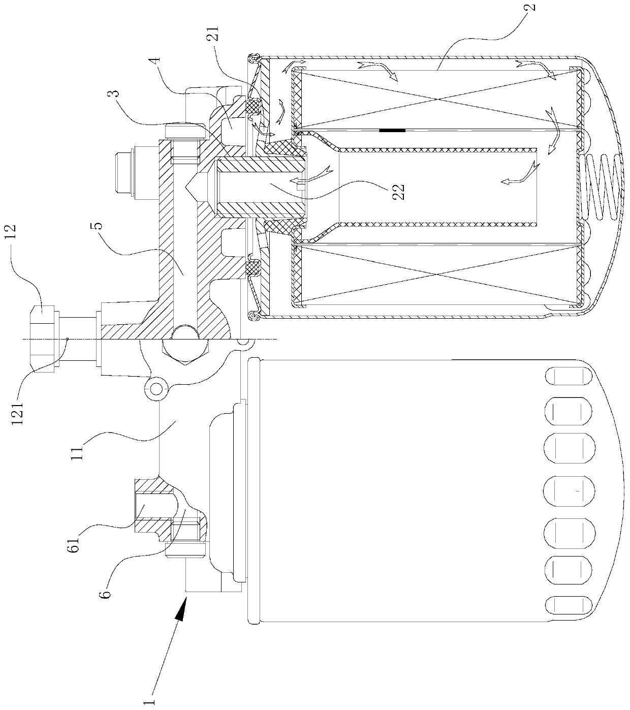
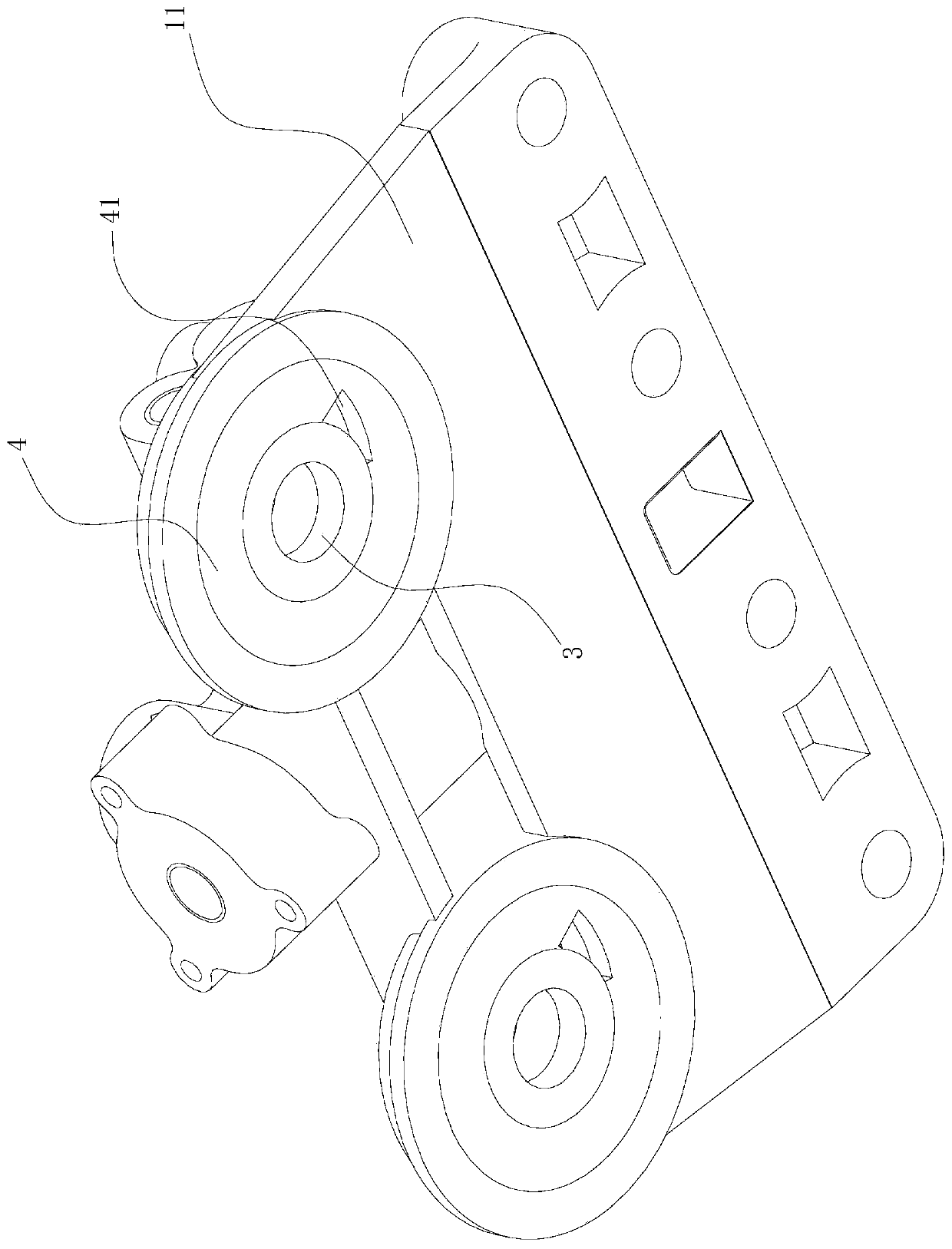
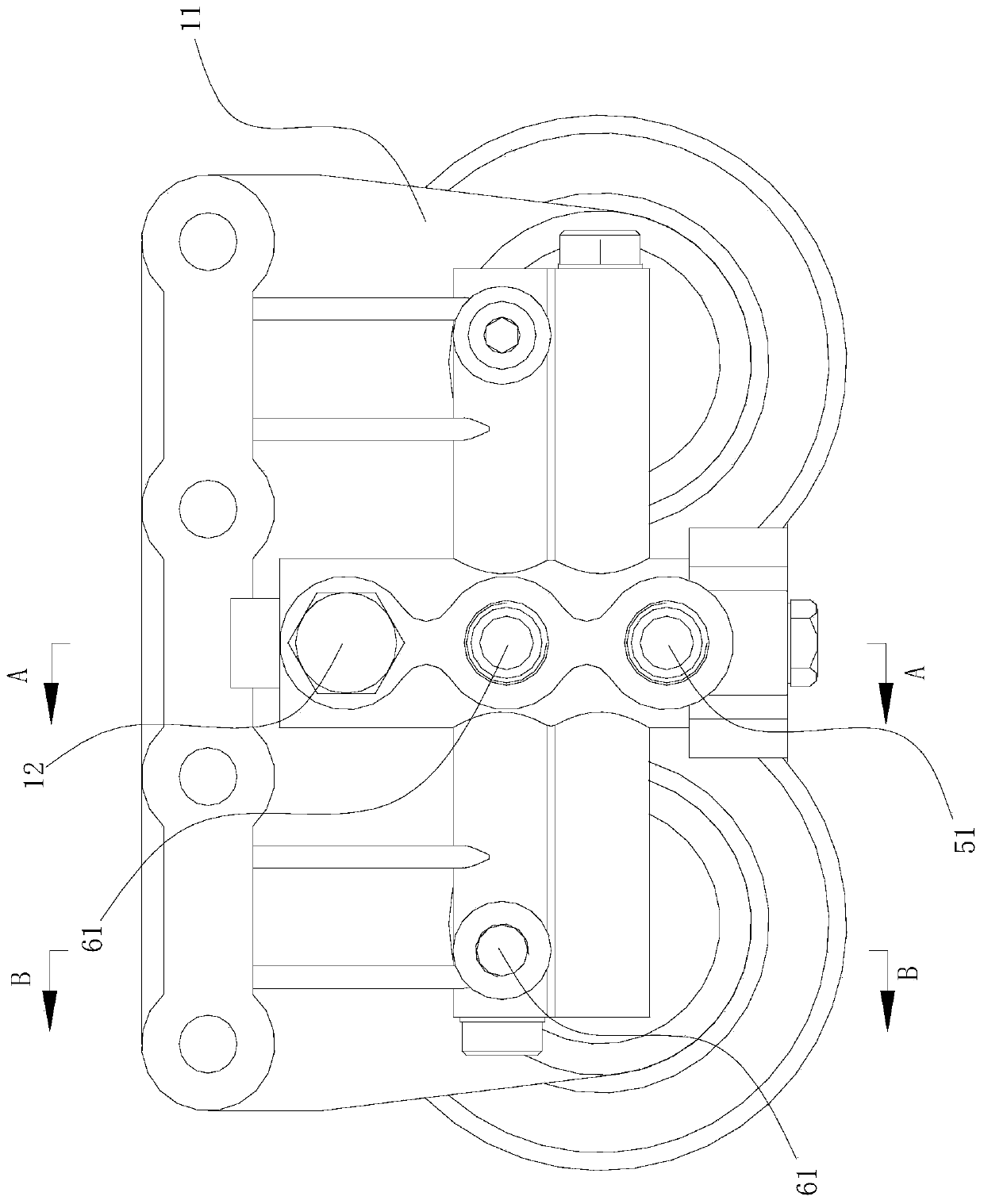
[0016] see Figure 1-Figure 5 , a large-flow fuel fine filter assembly, including a filter seat subassembly 1 and two fuel filter elements 2, the filter seat subassembly 1 includes a filter seat body 11, and the front part of the lower side of the filter seat body 11 There are two left-right symmetrical and vertically arranged threaded holes 3, and an annular groove 4 arranged around the threaded holes 3 is provided at the front position of the lower side of the filter seat body 11 corresponding to each threaded hole 3. The annular groove 4 The lower side is open, and the filter seat body 11 is provided with an oil outlet channel 5 and an oil inlet channel 6 that are arranged at intervals from front to back and are both left and right. The oil return channel 7 that is the same as the channel 6 and extends backward (in this embodiment, the oil inlet channel 6, the oil outlet channel 5, and the oil return channel 7 are all formed by drilling blind holes on the basis of the filte...


PUM


Abstract

The invention discloses a high-flow fuel fine filter assembly. The high-flow fuel fine filter assembly comprises a filter seat sub-assembly and two fuel fine filter elements, wherein the filter seat sub-assembly comprises a filter seat body; threaded holes are formed in the front portion of the lower side of the filter seat body; annular groove cavities are formed around the threaded holes; an oiloutlet channel and an oil inlet channel are formed in the filter seat body; an oil return channel is formed in the rear side of the oil inlet channel; the upper sides of the threaded holes are communicated with the oil outlet channel; through holes for communicating the annular groove cavities with the oil inlet channel are formed in the annular groove cavities; an oil outlet, an oil inlet and anoil return hole are formed in the upper side of the filter seat body; the oil outlet is communicated with the oil outlet channel; the oil inlet is communicated with the oil inlet channel; the oil return hole is communicated with the oil return channel; a bleeder screw is connected to the oil return hole; the two fuel fine filter elements are screwed on the two threaded holes respectively; oil outlets of the fuel fine filter elements are opposite to the threaded holes; oil inlets of the fuel fine filter elements are opposite to the annular groove cavities. The filter assembly is characterizedby high flow and also has an exhaust function.

Description

technical field [0001] The invention relates to a large-flow fuel fine filter assembly. Background technique [0002] At present, the emission standard of non-road diesel engines has been upgraded from China III to China IV, so that compared with the emission requirements of non-road China III, the equipped fuel filter not only improves the efficiency of impurity filtration and dust holding capacity, but also has a long life and reliability. Higher requirements are also put forward for the strengthening of functions such as safety and convenience. The injection pressure of the electronically controlled fuel system can generally reach 140-180Mpa. If such a high and stable oil pressure is required, sufficient fuel supply must be required. When the pressure rises, the temperature of the fuel will rise sharply, and the higher temperature will lead to a decrease in the lubricating performance of the fuel (the lubrication of the nozzle and the pump is mainly lubricated by diesel o...

Claims


Application Information

Patent Timeline
Patent Type & Authority Applications(China)
IPC IPC(8): F02M37/54F02M37/32
CPCF02M37/32F02M37/54
Inventor 单梅梅孙龙朱辉王磊
Owner 蚌埠国威滤清器有限公司
Learn More