
Spliced ring main unit and usage method thereof

A ring network cabinet and splicing technology, applied in the field of ring network cabinets, can solve the problems of ring network cabinet damage, easily damaged devices, ring network cabinets prone to offset, etc., and achieve the effect of avoiding offset and damage to wires.

Active Publication Date: 2020-02-21
ANHUI MINGKUN ELECTRICAL APPLIANCE EQUIP
View PDF10 Cites 4 Cited by
  • Summary
  • Abstract
  • Description
  • Claims
  • Application Information

AI Technical Summary

Problems solved by technology

[0004] The main purpose of the present invention is to provide a splicing ring network cabinet and its use method. This device mainly solves the following technical problems: splicing ring network cabinets of different sizes in the external environment is easy to damage the entire device, and the ring network cabinet during the splicing process It is prone to offset, and the ring network cabinets are prone to collisions during the movement of the ring network cabinets, which will cause damage to the ring network cabinets. The wires connected between the ring network cabinets are not protected and are prone to damage

Method used


Image

  • Spliced ring main unit and usage method thereof
  • Spliced ring main unit and usage method thereof
  • Spliced ring main unit and usage method thereof

Examples


Embodiment 1

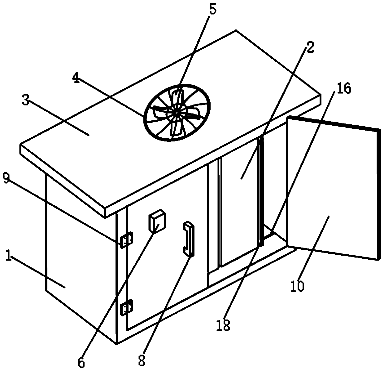
[0030] Such as Figure 1-6As shown, a spliced ​​ring network cabinet includes a cabinet body 1 and three ring network cabinets 2, and the three ring network cabinets 2 are located inside the cabinet body 1. A shielding cover 3 is provided on the upper end of the cabinet body 1, and the shielding cover 3 A fan 5 is installed on the upper end, and a protective cover 4 is arranged on the cover 3 above the fan 5. The protective cover 4 can protect the fan 5 and prevent larger objects from entering the inside of the cabinet 1. The two front ends of the cabinet 1 Both sides are provided with two hinges 9, and the two hinges 9 on the same side are connected with a box door 10, and a handle 8 is fixedly installed on the box door 10, and a PLC controller 6 is arranged on one of the box doors 10, and the PLC control The device 6 is located on one side of the handle 8. A temperature sensor 7 is installed on the inner upper end of the cabinet body 1. Two sets of No. 1 chutes 16 are provid...

Embodiment 2

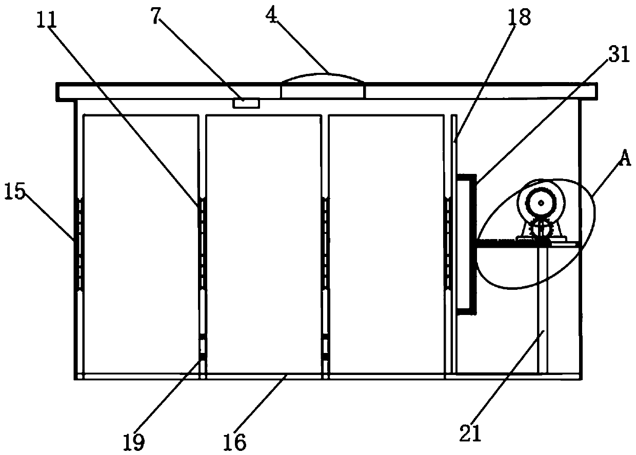
[0036] Such as Figure 1-6 As shown, a spliced ​​ring network cabinet includes a cabinet body 1 and three ring network cabinets 2. A support column 21 is fixedly installed on one side of the bottom end of the cabinet body 1, and a support plate 22 is fixedly connected to the upper end of the support column 21. , the upper end of the support plate 22 is provided with a channel 23, the channel 23 is equipped with a mounting plate 20, the upper end of the mounting plate 20 is fixedly connected with a rack 24, and the end of the mounting plate 20 away from the channel 23 is fixedly connected with a push rod 31, close to the ring The upper and lower ends of the push rod 31 on one side of the network cabinet 2 are fixedly connected with the push plate 18, and the end of the installation plate 20 close to the channel 23 on the inner wall of the cabinet body 1 is provided with a rubber block 25. The setting of the channel 23 can make the rack 24 move inside the channel 23 , to prevent...

Embodiment 3

[0041] The invention provides a method for using a spliced ​​ring network cabinet, the specific steps are as follows:

[0042] Step 1: Place the cabinet 1 at the set position, install the cover 3 on the upper end of the cabinet 1, install the fan 5 on the cover 3, and install the protective cover 4 on the cover 3 above the fan 5 At the upper end of the upper end, install the two door 10 on one side of the cabinet body 1 through the hinge 9, then install the handle 8 on the door 10 respectively, install the PLC controller 6 on one of the door 10, and The temperature sensor 7 is installed on the upper end of the cabinet 1 on the side close to the fan 5;

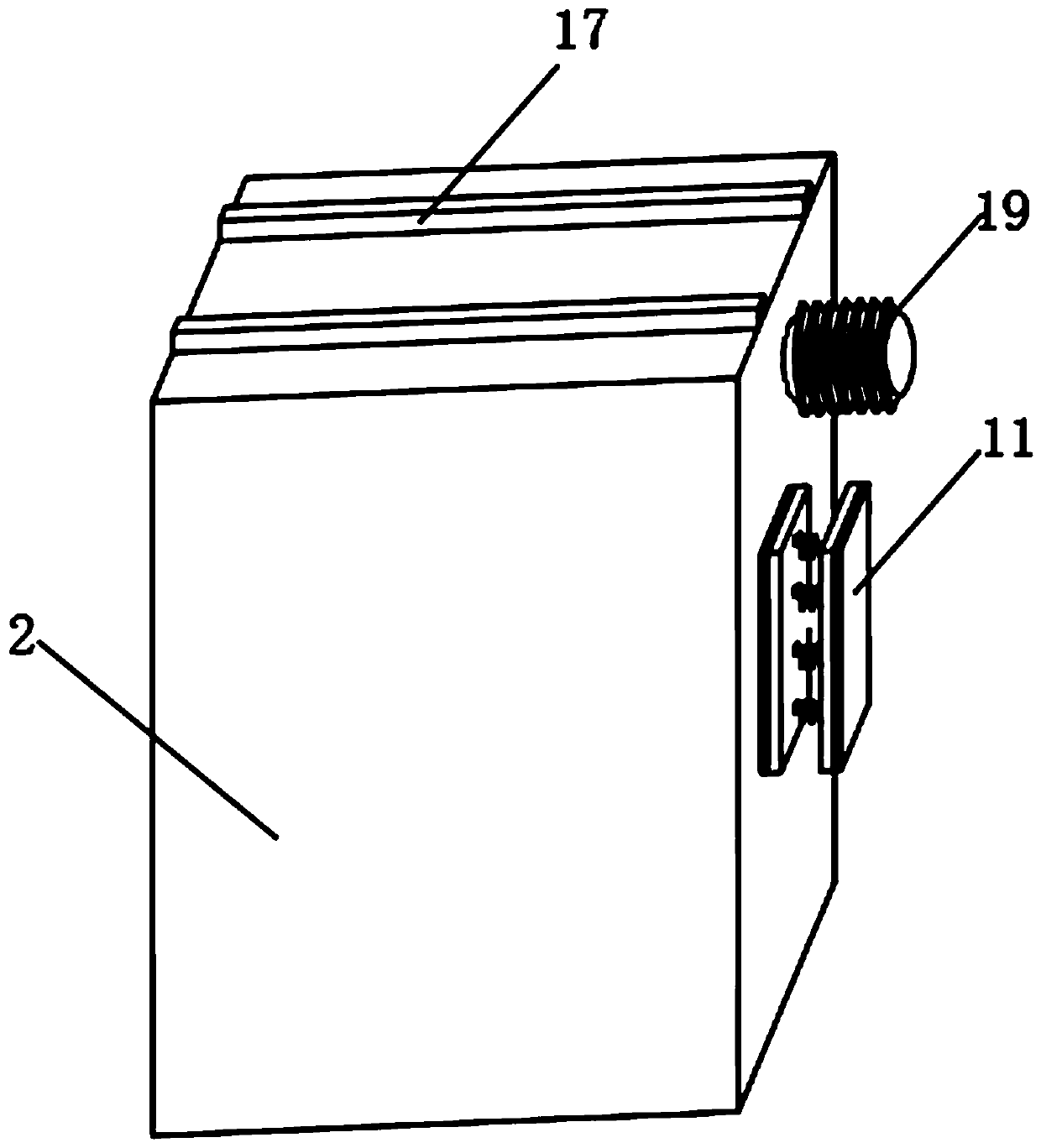
[0043] Step 2: Install the No. 2 buffer device 15 on the inner wall side of the cabinet body 1, and then install the No. 1 buffer device 11 and the telescopic hose 19 on the same side of the ring network cabinet 2, and the telescopic hose 19 is located on the No. 1 buffer device. 11, then two groups of No. 1 slide bars 17 are ...


PUM


Abstract

The invention discloses a spliced type ring main unit. The ring main unit comprises a cabinet body and three ring main units. The three ring main units are located in the cabinet body. A shielding cover is arranged at an upper end of the cabinet body. A fan is installed at the upper end of the shielding cover. A protective cover is arranged on the shielding cover above the fan. Two groups of number one sliding grooves are arranged in a bottom end of an internal portion of the cabinet body, two groups of number one sliding rods are fixedly connected to lower ends of the three ring main units, the three ring main units are slidably connected with the bottom end of the cabinet body through the two groups of number one sliding rods and the number one sliding grooves, and a number one buffer device is arranged on one side of each of the three ring main units. By using the spliced ring main unit and the using method thereof, the ring main units of different sizes can be fixedly spliced in the cabinet body, the ring main units can move in one direction in a splicing process, a buffering effect is achieved in a ring main unit moving process, an effect of protecting the ring main units andthe cabinet body can be achieved, and practical performance is achieved.

Description

technical field [0001] The invention relates to the technical field of ring network cabinets, in particular to a spliced ​​ring network cabinet and a method for using the same. Background technique [0002] With the continuous and rapid development of my country's social economy and the continuous improvement of people's living standards, power users have put forward higher requirements for power supply reliability, power quality and power supply security. The smart distribution network that is vigorously promoted in China is developing rapidly. As the main power equipment of the smart distribution network, the ring main unit can greatly improve the reliability and economy of power supply of the distribution network, reduce labor intensity, improve management level and service Quality, to promote the development of intelligent distribution network, the ring network cabinet is a group of transmission and distribution electrical equipment (high-voltage switchgear) installed in...

Claims


Application Information

Patent Timeline
Patent Type & Authority Applications(China)
IPC IPC(8): H02B1/30H02B1/54H02B3/00
CPCH02B1/308H02B1/54H02B3/00
Inventor 刘长胜
Owner ANHUI MINGKUN ELECTRICAL APPLIANCE EQUIP
Learn More