
Alignment test method for rate biasing laser gyroscope inertial navigation system based on dual-shaft turntable

A dual-axis turntable, rate-biasing technology, applied in the field of laser gyro inertial navigation system testing, can solve the problems affecting the alignment accuracy of the laser gyro inertial navigation system, long debugging period, complicated operation, etc., to increase the test efficiency and degree of automation , reduce time and technical costs, and achieve the effect of rate offset frequency

Inactive Publication Date: 2020-02-21
BEIJING AEROSPACE ERA LASER NAVIGATION TECH CO LTD
View PDF5 Cites 2 Cited by
  • Summary
  • Abstract
  • Description
  • Claims
  • Application Information

AI Technical Summary

Problems solved by technology

At present, the jitter bias technology is the most widely used, but the reciprocating jitter will introduce random walk errors, which will affect the alignment accuracy of the laser gyro inertial navigation system
The rate bias frequency technology overcomes the influence of random walk error and can improve the alignment accuracy of the laser gyro inertial navigation system. At present, this technology is still in the testing and verification stage
[0003] By designing the test method, providing rate-biased excitation, verifying the alignment algorithm accuracy of the rate-biased laser gyro inertial navigation system, for the verification of the alignment algorithm of the rate-biased laser gyro inertial navigation system, the existing test technology has a long debugging period , complex operation, low efficiency and other disadvantages

Method used


Image

  • Alignment test method for rate biasing laser gyroscope inertial navigation system based on dual-shaft turntable
  • Alignment test method for rate biasing laser gyroscope inertial navigation system based on dual-shaft turntable
  • Alignment test method for rate biasing laser gyroscope inertial navigation system based on dual-shaft turntable

Examples


Embodiment Construction

[0034] The present invention will be further described in detail below in conjunction with the accompanying drawings and specific embodiments.

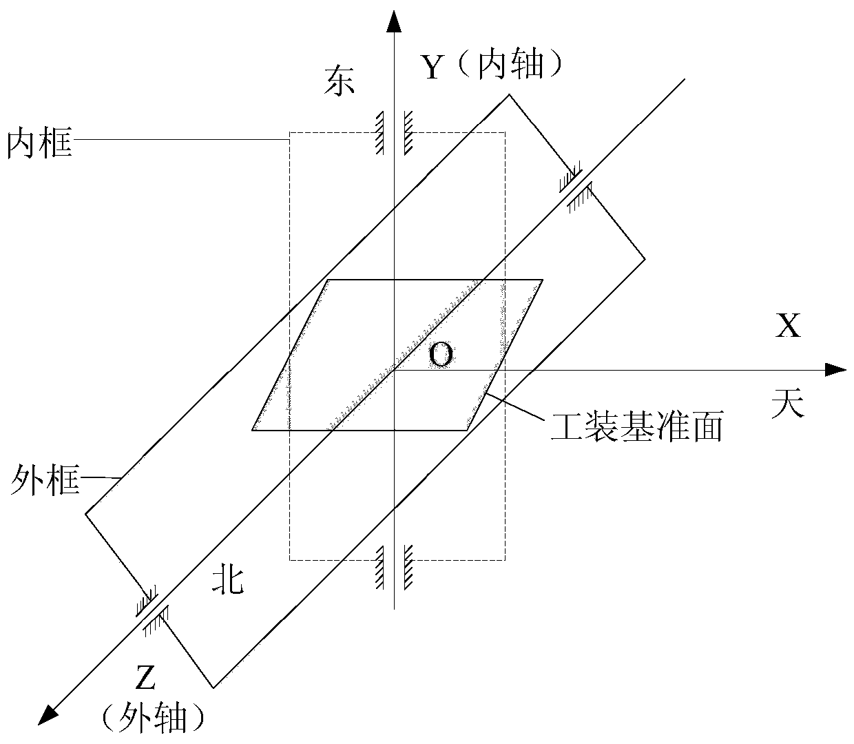
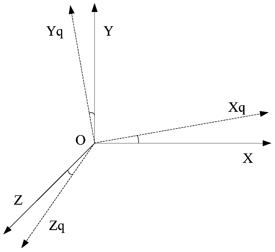
[0035] The present invention is an alignment test method for a rate-biased laser gyro inertial navigation system based on a double-axis turntable. The corresponding relationship of the navigation coordinate system of the rate-biased laser gyro inertial navigation system; (2) According to the communication protocol of the dual-axis turntable, the homing of the dual-axis turntable is realized; Tested two-axis turntable rotation requirements and turntable communication protocol and steps (1) The corresponding relationship between the inner axis and outer axis of the two-axis turntable and the navigation coordinate system of the rate-biased laser gyro inertial navigation system controls the rotation of the turntable to provide rate-biased frequency (4) After the inertial navigation system enters the rate bias working state, collect the pu...


PUM


Abstract

The invention discloses an alignment test method for a rate biasing laser gyroscope inertial navigation system based on a dual-shaft turntable. The alignment method comprises the following steps: (1)acquiring corresponding relationships between an inner shaft as well as an outer shaft of a dual-shaft turntable and a navigational coordinate system of a rate biasing laser gyroscope inertial navigation system; (2) realizing null seeking of the dual-shaft turntable; (3) controlling the rotating of the turntable according to the rotating requirement of the double-shaft turntable of an alignment test, a turntable communication protocol, and the corresponding relationships between the inner shaft as well as the outer shaft of the dual-shaft turntable and the navigational coordinate system of therate biasing laser gyroscope inertial navigation system; (4) after the inertial navigation system enters a rate biasing working state, acquiring pulse increment data of an inertial device of a gyroscope inertial navigation system in a rotating process of the dual-shaft turntable according to a certain period; (5) inputting the pulse increment data into an alignment interface of the rate biasing laser gyroscope inertial navigation system periodically, and performing online aligning; and (6) displaying and storing the online aligning data of the step (5).

Description

technical field [0001] The invention relates to an alignment test method for a rate-biased laser gyro inertial navigation system based on a two-axis turntable, and belongs to the technical field of laser gyro inertial navigation system testing. Background technique [0002] Lock-up effect is the main error source of laser gyroscope and becomes the main factor affecting the accuracy of laser gyroscope inertial navigation system. Jitter bias and rate bias are effective methods to control the locking effect of laser gyro inertial navigation system. The jitter bias uses alternating mechanical jitter to make the laser gyroscope work outside the locked area for a high proportion of time. The rate bias is to add a constant angular rate much larger than the lock threshold to the sensitive axis of the laser gyro, so that the output value of the total sensitive angular rate of the gyro is greater than the lock threshold. At present, the jitter bias technology is the most widely used...

Claims


Application Information

Patent Timeline
Patent Type & Authority Applications(China)
IPC IPC(8): G01C25/00
CPCG01C25/005
Inventor 宋腾腾
Owner BEIJING AEROSPACE ERA LASER NAVIGATION TECH CO LTD
Learn More