Energy gathering disk
A technology of energy-gathering disks and disks, which is applied in the direction of gas fuel burners, combustion methods, and combustion types, can solve problems such as shaking and annealing, and achieve the goals of improving service life, small inner cavity space, and improving installation stability Effect
- Summary
- Abstract
- Description
- Claims
- Application Information
AI Technical Summary
Problems solved by technology
Method used
Image

Examples
Embodiment approach 1
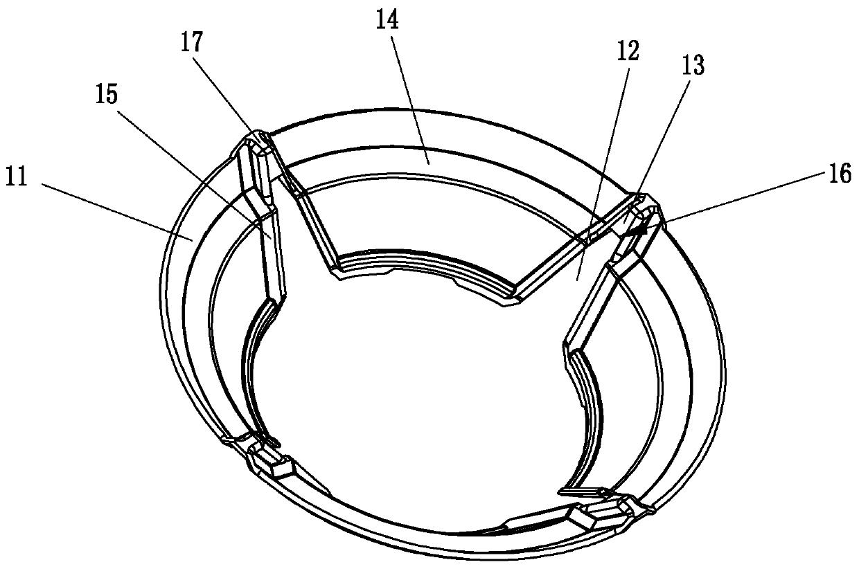
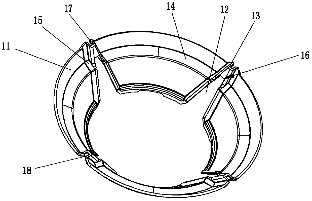
[0030] Embodiment 1: The disc body 11 is a thin-walled cylinder with a trumpet-shaped inner cavity. The inner diameter of the bottom end of the disc body is smaller than that of the top end. A slot 12 with an opening on the bottom side and radial penetration is provided on the disc body for clamping the hob rack. The number of slots of the commonly used energy-concentrating plate is 4 and 5, and the plate body is connected by a connecting section 13 on the top of the slot, and the connecting section protrudes radially inward, and the top of the connecting section is formed There are protrusions 17 protruding upwards, and the bottom surface of the connecting section forms a supporting surface 16 pressed against the support feet of the hob. In addition, the inner diameter of the disc body increases stepwise from the bottom end to the top end, and at least one layer of transverse stepped end surface 14 is formed on the inner side of the disc body. The cavity space is as small as ...
Embodiment approach 2
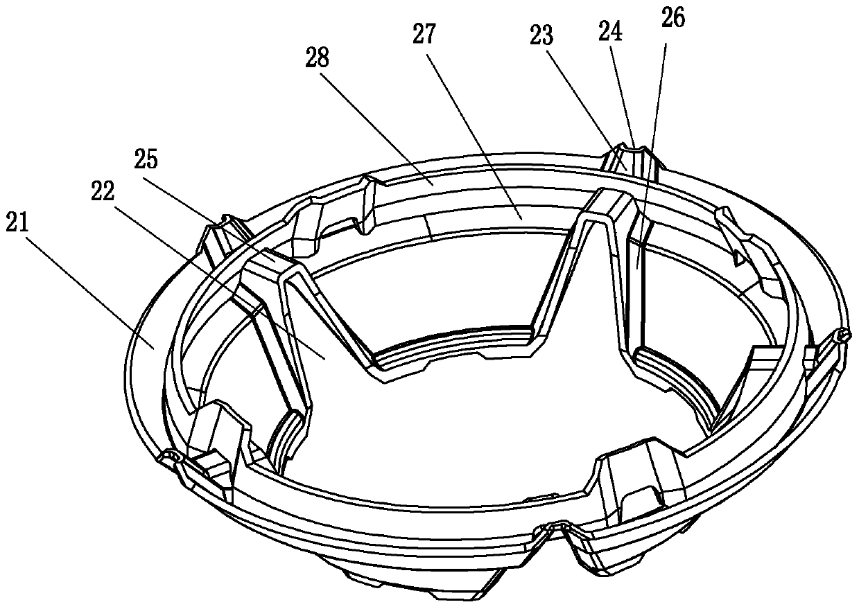
[0032] Implementation mode two: if Figure 3-Figure 4 As shown, the disc body 21 is a thin-walled cylinder with a trumpet-shaped inner cavity, the inner diameter of the bottom end of the disc body is smaller than the top end, and a slot 22 with an opening on the bottom side and radially penetrating through the disc body is used for clamping the hob rack. The number of slots for pot supports is usually 4 or 5, and the disc body is connected by a connecting section 23 on the top of the slot. The connecting section protrudes radially inward, and the bottom side of the connecting section radially Extend inwardly to form a pressing part 25, the bottom surface of the connecting section and the bottom surface of the pressing part form a supporting surface that is pressed against the support feet of the grate, and the distance between the top of the pressing part is reduced by the inward extension of the pressing part to ensure that it can be pressed against the pot. There are support...
Embodiment approach 3
[0034] Implementation mode three: if Figure 5As shown, the disc body 31 is a thin-walled cylinder with a trumpet-shaped inner cavity, the inner diameter of the bottom end of the disc body is smaller than the top end, and a slot 32 with a bottom side opening and radially penetrating through the disc body is used for clamping the hob rack. The number of slots for pot supports is usually 4 and 5. The disc bodies are connected by connecting sections 33 on the top of the slots. The connecting sections protrude radially inward, and the top of the connecting section is formed to protrude upwards. The bottom side of the connecting section extends radially inward to form a pressing part 35, and the bottom surface of the connecting section and the bottom surface of the pressing part form a supporting surface pressed against the support leg of the grate. Flanges are formed on the inner parts of both sides of the slot, and the flanges are connected with the pressing part. An inclined su...
PUM
 Abstract
Description
Claims
Application Information
 - R&D
- Intellectual Property
- Life Sciences
- Materials
- Tech Scout
- Unparalleled Data Quality
- Higher Quality Content
- 60% Fewer Hallucinations
Browse by: Latest US Patents, China's latest patents, Technical Efficacy Thesaurus, Application Domain, Technology Topic, Popular Technical Reports.
© 2025 PatSnap. All rights reserved.Legal|Privacy policy|Modern Slavery Act Transparency Statement|Sitemap|About US| Contact US: help@patsnap.com