
Concrete spreading trolley, concrete spreader and trolley

A cloth trolley and car body technology, which is applied in earthwork drilling, shaft lining, tunnel lining, etc., can solve the problems of heavy workload and labor intensity, cumbersome operation, and long time consumption, so as to improve pouring efficiency, ensure pouring quality, The effect of easy operation

Pending Publication Date: 2020-02-21
HUNAN WUXIN TUNNEL INTELLIGENT EQUIP CO LTD
View PDF0 Cites 2 Cited by
  • Summary
  • Abstract
  • Description
  • Claims
  • Application Information

AI Technical Summary

Problems solved by technology

[0003] Since the tunnel surface is divided into side and top, it is also necessary to consider side pouring and top pouring when pouring. The defects of the existing concrete placing machine are: (1) the pipeline system has only one discharge pipe, each Only a single window pouring can be completed. For different inlets of the same layer or inlets of different layers, it is necessary to disassemble and replace the pump pipe to complete the pouring. The operation is cumbersome; (2) In layered pouring construction, the same level The multiple feed inlets arranged in (layer) cannot be fed at the same time, which is prone to problems such as pouring height difference and excessive concrete flow distance and segregation; (3) side pouring and top pouring need to replace multiple pipes, workload and labor intensity big, long

Method used


Image

  • Concrete spreading trolley, concrete spreader and trolley
  • Concrete spreading trolley, concrete spreader and trolley

Examples


Embodiment 1

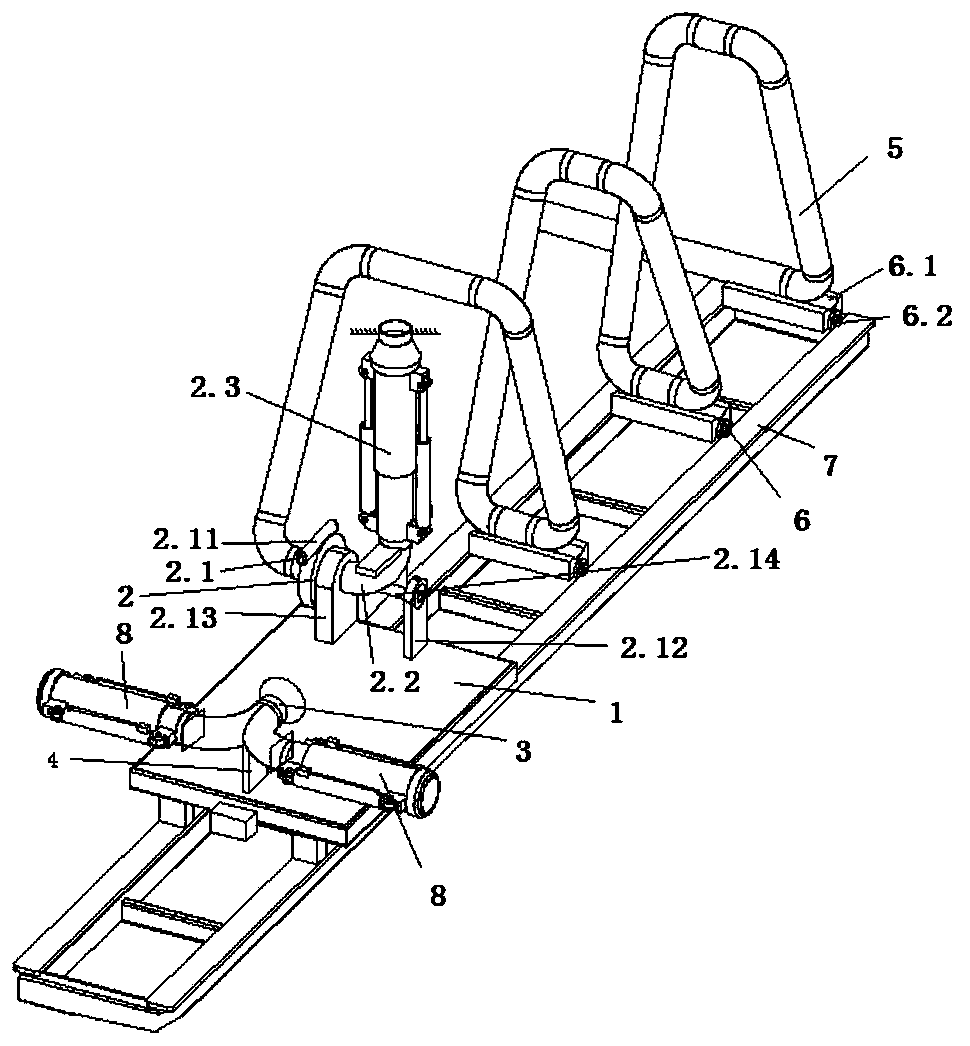
[0035] A concrete distributing machine, including a distributing trolley and a walking track 7 that facilitates the walking of the distributing trolley. The distributing trolley includes a car body 1, a rotating and telescopic connecting pipe 2, a discharge pipe 3 and a feeding pipe 5. For details, see figure 1 ,Details are as follows:

[0036] The car body 1 of the cloth trolley can walk back and forth along the walking track 7, and is used to drive the rotating telescopic connecting pipe 2, the discharge pipe 3 and the feeding pipe 5 to move, and the car body can be provided with a walking track that matches the walking track 7 Parts (such as roller sets), the cloth trolley can also include power components, and the power can be mechanical (oil cylinder, cylinder, fuel oil, gas, etc.), and the cloth trolley can also be manually driven to walk.

[0037] The feed pipe 5 includes at least two stretchable single pipes arranged in series, and the adjacent single pipes are movably...

Embodiment 2

[0048] A trolley, comprising the concrete placing machine as described in Embodiment 1, the placing trolley of the concrete placing machine is arranged on the walking track on the door frame of the trolley.


PUM


Abstract

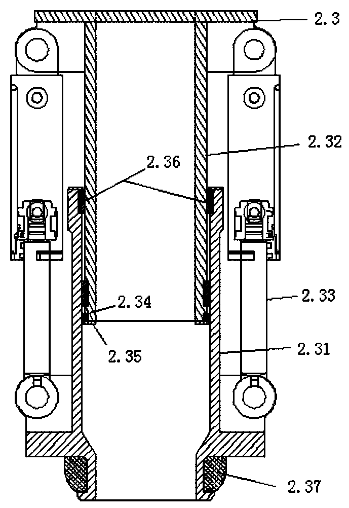
The invention provides a concrete spreading trolley. The concrete spreading trolley comprises a vehicle body, a rotary telescopic connecting pipe and a discharging pipe, wherein the rotary telescopicconnecting pipe and the discharging pipe are arranged on the vehicle body, and the rotary telescopic connecting pipe comprises a rotary mechanism, a bent pipe and a telescopic sleeve pipe; the discharging pipe is a herringbone pipe or a Y-shaped pipe formed by one first section pipe and two second section pipes. The concrete spreading trolley has the following effects that firstly, the structure is simplified, namely through arranging the rotary telescopic connecting pipe, the rotary mechanism in the rotary telescopic connecting pipe can drive the bent pipe and the telescopic sleeve pipe to rotate, so that the requirements of side pouring and top pouring are met; secondly, the telescopic sleeve pipe can stretch and retract to meet the requirements of different pouring distances; and thirdly, the discharging pipe adopts the herringbone pipe or the Y-shaped pipe, so that lateral multi-window simultaneous pouring is achieved, the pouring efficiency is improved, and the pouring quality canbe ensured. The invention further discloses a concrete spreader which comprises the concrete spreading trolley. The invention further discloses a trolley which comprises the concrete spreader.

Description

technical field [0001] The invention relates to the technical field of concrete distribution, in particular to a distribution trolley, a concrete distribution machine and a trolley. Background technique [0002] Concrete pouring is involved in the tunnel construction technology, and the existing concrete pouring is all completed by concrete placing machines. [0003] Since the tunnel surface is divided into side and top, it is also necessary to consider side pouring and top pouring when pouring. The defects of the existing concrete placing machine are: (1) the pipeline system has only one discharge pipe, each Only a single window pouring can be completed. For different inlets of the same layer or inlets of different layers, it is necessary to disassemble and replace the pump pipe to complete the pouring, and the operation is cumbersome; (2) In layered pouring construction, the same level The multiple feed inlets arranged in (layer) cannot be fed at the same time, which is p...

Claims


Application Information

Patent Timeline
Patent Type & Authority Applications(China)
IPC IPC(8): E21D11/10
CPCE21D11/10E21D11/105
Inventor 王祥军龚俊曾勇赖光有王慧民
Owner HUNAN WUXIN TUNNEL INTELLIGENT EQUIP CO LTD
Learn More