
Precise positioning and measuring method for constructing cast-in-situ bored pile

A bored-in-place pile, precise positioning technology, applied in sheet pile wall, foundation structure engineering, foundation structure test, etc. problems, to achieve the effect of improving the level of construction quality, improving the construction progress, and improving the accuracy of positioning

Inactive Publication Date: 2020-02-21
STATE GRID CORP OF CHINA +1
View PDF7 Cites 2 Cited by
  • Summary
  • Abstract
  • Description
  • Claims
  • Application Information

AI Technical Summary

Problems solved by technology

The error of the above method is large. When the wind speed is high, the lead pendant will swing irregularly and cannot be accurately aligned with the center of the pit, resulting in an error. In this way, the center of the main column of the poured concrete foundation and the center of the anchor bolt will cause a large deviation major defect
In addition, this measurement method cannot be used at night and in poor weather measurement construction, and the low work efficiency reduces electricity sales

Method used


Image

  • Precise positioning and measuring method for constructing cast-in-situ bored pile
  • Precise positioning and measuring method for constructing cast-in-situ bored pile
  • Precise positioning and measuring method for constructing cast-in-situ bored pile

Examples


Embodiment Construction

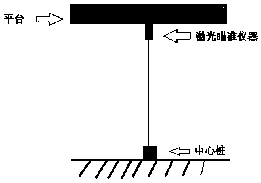
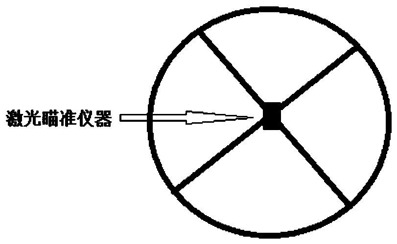
[0015] The specific implementation manner of the present invention will be described in detail below in conjunction with the accompanying drawings and preferred embodiments. Such as Figure 1-3 As shown, the present invention introduces a method for precise positioning and measurement of bored pile construction, comprising the following steps:

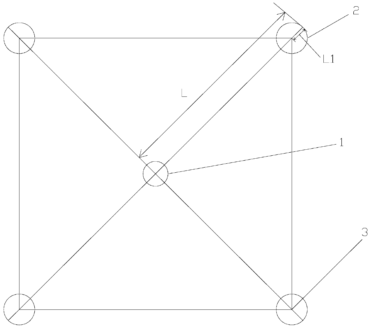
[0016] Step 1: In the form of a square foundation, put the theodolite on the central pile 1, and the central pile is located in the center of the square, as shown in figure 1 As shown, align the theodolite with the direction pile and rotate it at an angle of 45 degrees to accurately find out the four directions, and use a steel tape to pull the half-diagonal length L to find four pits in the 45-degree direction around the center pile 2; four pits After the general position of the pit is found, the center point of the pit has not been found, and it is found through step 2.

[0017] Step 2: The pile head is fixed with two semi-circular...


PUM


Abstract

The invention relates to the technical field of building construction, in particular to a precise positioning and measuring method for constructing a cast-in-situ bored pile. The method includes the following steps that firstly, according to the form of a square foundation, a theodolite or total station is erected on a central pile and aligned with an alignment stake to be rotated by 45 degrees, and four pit sites are found in 45-degree directions around the central pile correspondingly after a steep tape is pulled by a half diagonal length; secondly, a pile head is fixed by sizing two semicircular formworks, and the centers of the four pit sites are obtained by subtracting the radius of the pile from the half diagonal length of the square foundation are obtained; thirdly, a laser sight isfixedly installed at the center of a drill bit platform of a drilling machine; fourthly, a reinforcement cage is immediately put down after drilling is completed, and immediately concrete is poured;and fifthly, foundation bolts are installed after concrete is poured, the third step is executed again, and the centers of the foundation bolts completely coincide with the centers of the pit sites through the laser sight. The method is not limited by the environment temperature, humidity, light and other objective influencing environmental factors and can greatly improve the positioning precisionand reduce errors.

Description

technical field [0001] The invention relates to the technical field of building construction, in particular to a precise positioning and measuring method for bored pile construction. Background technique [0002] In the construction process of the bored pile foundation of the line, it is difficult to control the eccentricity of the main column of the foundation. The conventional deviation control method is to hang a lead pendant on the center of the drill platform before drilling to start drilling when it coincides with the center pile of the pit. A metal cone weight, ie, a lead weight. When centering, the natural drooping lead pendant of the translational drill platform coincides with the center of the pit on the ground, which is the centering. The error of the above method is large. When the wind speed is high, the lead pendant will swing irregularly and cannot be accurately aligned with the center of the pit, resulting in an error. In this way, the center of the main co...

Claims


Application Information

Patent Timeline
IPC IPC(8): E02D5/34E02D33/00
CPCE02D5/34E02D33/00
Inventor 吴善勇
Owner STATE GRID CORP OF CHINA
Learn More