
Device for early warning of structure damage according to stress monitoring

A stress monitoring and structure technology, applied in textiles, papermaking, textile cables, etc., can solve the problems of slow update rate, poor robustness, and complicated operation, and achieve the effect of ensuring reliability, reasonable design and convenient operation.

Active Publication Date: 2020-02-21
舟山天沐水产科技有限公司
View PDF5 Cites 3 Cited by
  • Summary
  • Abstract
  • Description
  • Claims
  • Application Information

AI Technical Summary

Problems solved by technology

This kind of measurement system has a large volume, so it has a great impact on the structure of the monitored object, and at the same time, the measurement accuracy for large deformation cannot meet the positioning requirements
At the same time, the positioning system of underwater robots is based on acoustics. This system is complex to operate, and has the disadvantages of slow update rate, poor robustness to coastal noise interference, and poor autonomy.

Method used


Image

  • Device for early warning of structure damage according to stress monitoring
  • Device for early warning of structure damage according to stress monitoring
  • Device for early warning of structure damage according to stress monitoring

Examples


Embodiment 1

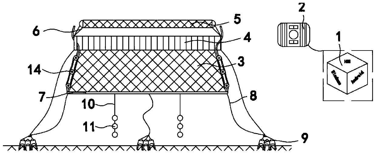
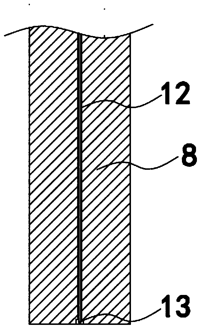
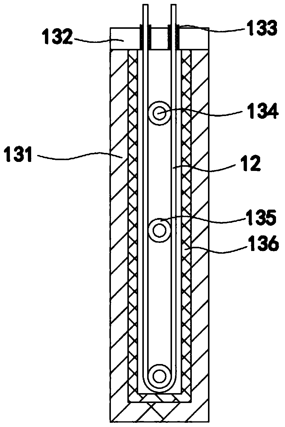
[0027] like Figure 1-6 As shown, a device for early warning of structural damage based on stress monitoring includes a mobile terminal 1, a data processor 2, and a netting 3. The top of the netting 1 is connected to a top frame 4, and the bottom of the netting 1 is provided with a bottom frame 7. The bottom surface of the frame 7 is connected with the peripheral lower edge of the top frame 4 with a cable 8. The cable 8 is braided by multiple strands, and the inside of the cable 8 is woven with an optical fiber 12. 13 includes a top cover 132, the top cover 132 is connected to the housing 131 through threads, the top of the top cover 132 is symmetrically provided with an anti-wear sealing ring 133, and the inside of the housing 131 is provided with at least three fixed shafts 134 longitudinally, and each fixed shaft 134 is A rotating shaft 135 is sheathed, and a rubber layer 136 is adhered to the inner wall of the casing 131 . The cable of the present invention is internally ...

Embodiment 2

[0039] like Figure 1-6 As shown, the workflow of the device is as follows Figure 5 As shown: the cable 8 is connected at the edge of the lower end of the net 1 and the edge of the top frame 4, and then the cable 8 is tied to the anchor body 9, and the cable 8 at the bottom of the net 1 is impacted by waves and waves. The optical fiber 12 inside the cable 8 will check the tension of the cable 8 every time, and send the monitored raw data to the data processor 2 through wireless signal transmission, and the data processor 2 analyzes the raw data, technology, and then transmit the processed data to the mobile terminal 1 for display, and the operator analyzes and judges the output tension value, whether it exceeds the bearing capacity of the cable 8.


PUM


Abstract

The invention discloses a device for early warning of structure damage according to stress monitoring, comprising a mobile terminal, a data processor and a netting. A top frame is connected to the topof the netting, a bottom frame is arranged at the bottom of the netting, cables are connected to the lower edges of the bottom surface of the bottom frame and the outer periphery of the top frame; each cable is braided with multiple strands, and is braided with an optical fiber, and the bottom bend of the optical fiber is sleeved with a sheath; the sheath comprises a cap, the cap is connected with a casing through thread, anti-wear seal gaskets are symmetrically arranged on the top of the cap, at least three fixing shafts are arranged longitudinally inside the casing, each fixing shaft is sleeved with a rotary shaft, and a rubber layer is attached to the inner wall of the casing. Tension of the cables is monitored in real time by the device according to impact to the cables from sea waveand sea current, the tension to the cables is determined according to monitored data, and economic loss due to breakage of the cables caused by stress, which excesses the bearing capacity, of the cables is avoided.

Description

technical field [0001] The invention belongs to the technical field of monitoring and early warning, and in particular relates to a device for early warning of structural damage based on stress monitoring. Background technique [0002] The cable is an indispensable stress element and safety guarantee in marine breeding projects and various engineering constructions. The stress of the cable will greatly affect the safety of life, breeding safety and breeding benefits. Therefore, it is particularly important to monitor the tension of the cable . [0003] At present, the deformation monitoring of pipelines or cables is limited to small deformations, and resistive or capacitive devices are mostly used for fixed-point measurement. This kind of measurement system has a large volume, so it has a great influence on the structure of the monitored object, and at the same time, the measurement accuracy for large deformation cannot meet the positioning requirements. At the same time, ...

Claims


Application Information

Patent Timeline
Patent Type & Authority Applications(China)
IPC IPC(8): D07B1/14
CPCD07B1/145
Inventor 王萍冯德军桂福坤孙孟
Owner 舟山天沐水产科技有限公司
Learn More