Biogas fermentation system

A biogas fermentation and fermentation tank technology, applied in the field of biogas fermentation system, can solve the problems of unstable air pressure, incomplete discharge, poor sealing performance, etc., and achieve the effects of avoiding vibration and noise, improving emulsification effect and prolonging service life

Pending Publication Date: 2020-02-21
河南美丽乡村环保科技有限公司
View PDF0 Cites 0 Cited by
  • Summary
  • Abstract
  • Description
  • Claims
  • Application Information

AI Technical Summary

Problems solved by technology

[0003] At present, most of the rural areas use masonry cement or glass as materials to make biogas digesters. The disadvantages are: static fermentation is now used, the distribution of raw materials and microorganisms is uneven, the mixing degree of fermentation materials is poor, the fermentation effect is not good, and the reaction is not stable. The biogas pressure changes greatly, the air pressure is unstable, the combustion is very unstable, and the production of biogas takes a long time; the scum is easy to crust and easy to block; it needs to be manually removed from the bottom, and the discharge is not complete; the sealing performance is poor, and it is easy to leak; It is difficult to install and maintain; the gas storage capacity cannot be adjusted according to the amount of biogas liquid
Although the existing secondary sealing mechanism can improve the sealing effect of the biogas liquid to a certain extent and avoid the leakage and volatilization of the biogas liquid in the biogas tank, thereby causing waste, the scraper and the inner wall of the biogas tank will not achieve a complete seamless fit , a certain amount of biogas liquid will still escape

Method used


Image

  • Biogas fermentation system
  • Biogas fermentation system
  • Biogas fermentation system

Examples


Embodiment Construction

[0035] In order to make the technical solutions and advantages of the present invention clearer, the present invention will be further described in detail below in conjunction with the accompanying drawings and embodiments.

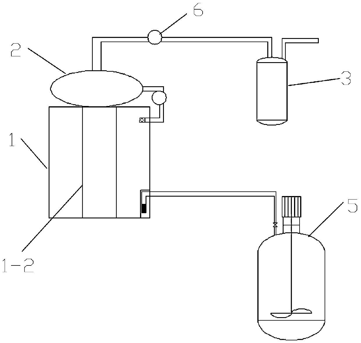
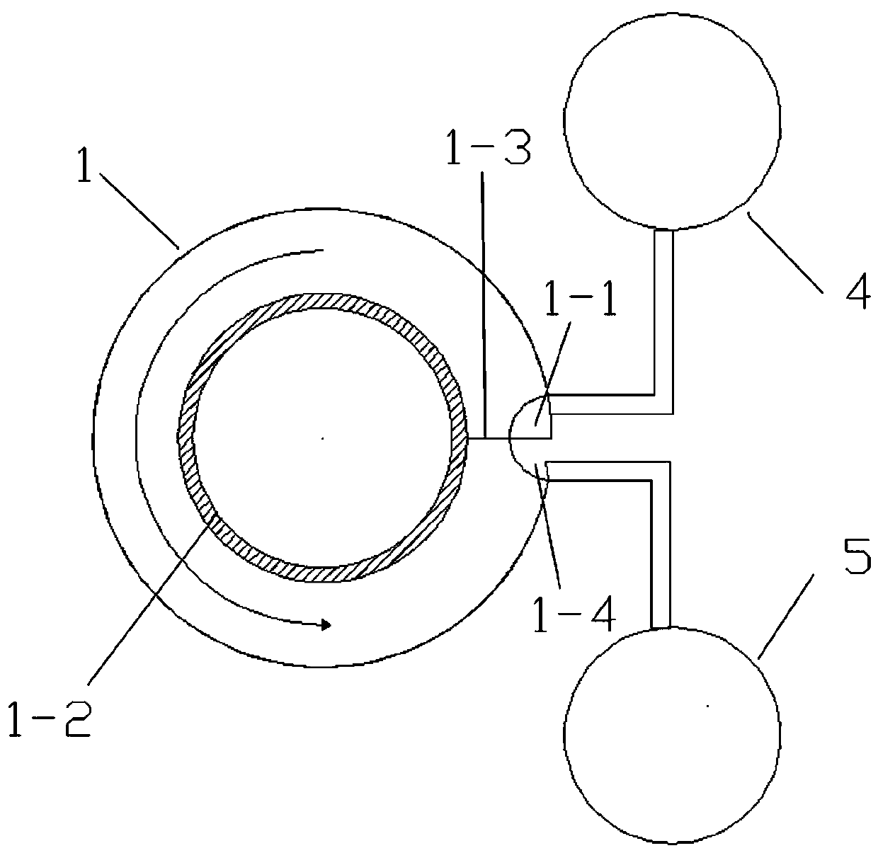
[0036] As shown in the figure: the embodiment of this scheme provides a biogas fermentation system, including a fermenter 1, a gas storage bag 2, a gas storage tank 3 and a biogas slurry storage tank 4, the fermenter 1 is a cylindrical tank structure, in One side wall of the fermenter 1 is provided with a feeding port 1-1 and a waste liquid discharge port 1-4, and an annular baffle 1-2 is arranged at the bottom of the fermenter 1 along the center, and the side wall of the fermenter 1 is connected to the annular baffle. A material circulation channel is formed between the baffles 1-2, and a partition plate 1-3 is provided at the feed port 1-1 in the material liquid flow channel to isolate the feed port 1-1 from the waste liquid discharge port 1-4 , the hei...


PUM


Abstract

The invention discloses a biogas fermentation system. The system comprises a fermentation tank, a gas storage bag, a gas storage tank and a biogas liquid storage tank, wherein the fermentation tank isof a cylindrical tank structure, the side wall of one side of the fermentation tank is provide with a feeding port and a waste liquid discharge port, an annular baffle plate is arranged along the center of the bottom of the fermentation tank, a material circulation channel is formed between the side wall of the fermentation tank and the annular baffle plate, and a partition plate is arranged at the material liquid circulation channel located at the feeding port, and is used for separating the feeding port from the waste liquid discharge port. The height of the bottom of the material circulation channel is gradually lowered from the feeding port to the waste liquid discharge port, so that the material automatically flows forward from the feeding port along the material circulation channel,and a pipeline above the side wall of the fermentation tank communicates with the gas storage bag. The apparatus improves the biogas fermentation system, fully optimizes the equipment, improves the tightness of the equipment, and turns the waste biogas liquid into treasure.

Description

technical field [0001] The invention belongs to the technical field of biogas fermentation, and in particular relates to a biogas fermentation system. Background technique [0002] With the progress and development of society, people's demand for energy is increasing. Biogas is a combustible gas produced by microbial fermentation of organic matter in an anaerobic environment under certain temperature, humidity, and pH conditions. gas. As a renewable energy source, biogas has been widely used in rural areas. At the same time, with the development of large-scale and intensive animal husbandry in my country, the number of large and medium-sized biogas projects is also increasing day by day, but it also brings a series of problems. . Whether it is a rural household biogas digester or a large and medium-sized biogas project, in addition to generating new energy-biogas, it will also produce a large amount of biogas slurry during operation. Because there are few methods for bioga...

Claims


Application Information

Patent Timeline
Patent Type & Authority Applications(China)
IPC IPC(8): C12M1/107C05F17/979C05F17/986C05F17/964C05F17/90
CPCC12M21/04C12M23/36C12M23/56C12M27/20C12M37/04Y02W30/40
Inventor 张建松
Owner 河南美丽乡村环保科技有限公司
Why Eureka
Try Eureka