
Flexible rack for material conveyor and belt conveyor

A conveyor and rack technology, applied in the field of flexible racks and belt conveyors for material conveyors, can solve the problems of lack of displacement compensation function and inability to meet the needs of complex use environments, so as to avoid insufficient connection strength and avoid The effect of deformation and large displacement compensation ability

Pending Publication Date: 2020-02-21
HUADIAN HEAVY IND CO LTD
View PDF6 Cites 2 Cited by
  • Summary
  • Abstract
  • Description
  • Claims
  • Application Information

AI Technical Summary

Problems solved by technology

[0003] Therefore, the technical problem to be solved by the present invention is to overcome the problem that the frame of the existing belt conveyor is a rigid structure, does not have a displacement compensation function, and cannot meet the needs of complex use environments

Method used


Image

  • Flexible rack for material conveyor and belt conveyor
  • Flexible rack for material conveyor and belt conveyor
  • Flexible rack for material conveyor and belt conveyor

Examples


Embodiment 1

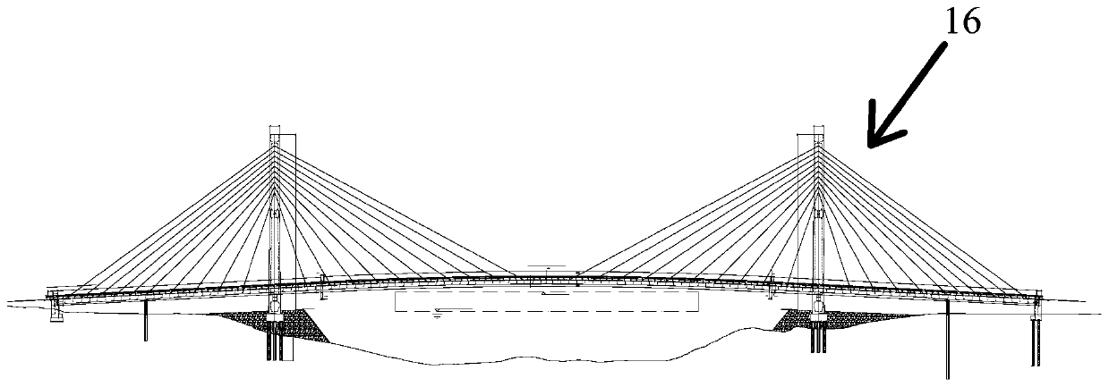
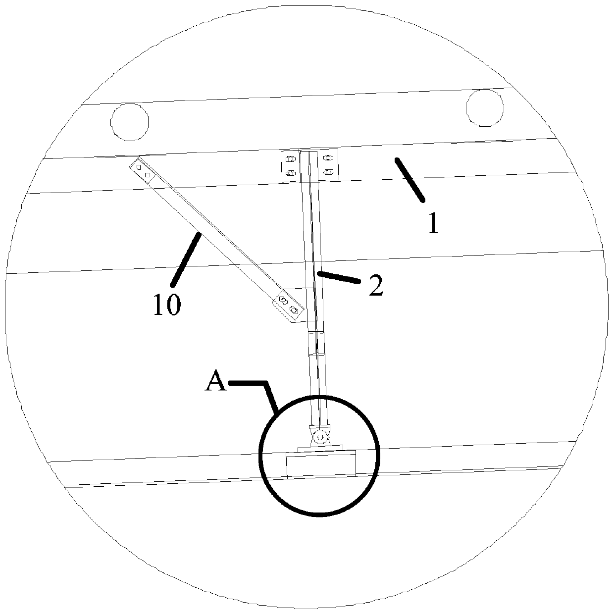
[0041] A belt conveyor with a flexible frame is described as figure 2 As shown, the belt conveyor is set on a longer river-crossing or sea-crossing cable-stayed bridge. The two ends of the above-mentioned bridge 16 are movable, and due to wind load, thermal expansion and contraction, etc. A linear displacement is produced, and a bending perpendicular to the axial direction of the bridge 16 is produced. The belt conveyor located on the above-mentioned bridge 16 has a flexible frame. flexible racks, such as figure 1 shown, which includes:

[0042] Rack body 1, such as Figure 7 As shown, the material is arranged on the frame body 1, and is driven to move to a designated position; the frame body 1 is a segmented structure, and the frame body 1 includes a middle frame 14, and the The end frame 15 at both ends of the middle frame 14; a telescopic gap is arranged between the middle frame 14 and the end frame 15, and the frame body 1 of the above-mentioned segmented structure ca...


PUM


Abstract

The invention relates to a flexible rack for a material conveyor and a belt conveyor. The flexible rack for the material conveyor comprises a rack body and supporting legs, wherein materials are arranged on the rack body and are driven to move to a specified position; at least two supporting legs are arranged, one end of each supporting leg is pivotally connected with a fixing base through a rotating shaft, the other end of each supporting leg is in sliding connection with a first strip-shaped hole through a first connecting part which is inserted in a matched mode, and the first strip-shapedholes are arranged along the length direction of the rack body. The plurality of supporting legs are arranged at the bottom of the rack body, one end of each supporting leg is pivotally connected withthe corresponding fixing base, and the other end of each supporting leg is in sliding connection with the corresponding first strip-shaped hole through the corresponding first connecting part, so that the problems that an existing belt conveyor is of a rigid structure and does not have a displacement compensation function and cannot meet the requirement of complex use environments are solved.

Description

technical field [0001] The invention relates to the technical field of conveyor equipment, in particular to a flexible frame for a material conveyor and a belt conveyor. Background technique [0002] The belt conveyor consists of a driving device, a tensioning device, a middle frame of the conveyor belt and an idler roller. It is a friction-driven machine that transports materials in a continuous manner. It can move materials on a certain conveyor line from the initial feeding point A material conveying process is formed between the final unloading point. Belt conveyors are widely used in various modern industrial enterprises. The existing traditional belt conveyor adopts a rigid connection method and cannot realize position compensation. For complex terrain, especially for medium and long-distance belt conveyors installed on bridges, due to bridge settlement and thermal expansion and contraction, the various parts of the belt conveyor are very prone to relative displaceme...

Claims


Application Information

Patent Timeline
IPC IPC(8): B65G41/00B65G21/14
CPCB65G41/00B65G21/14
Inventor 魏日波张战胜赵福付衡业刘皞赵勇
Owner HUADIAN HEAVY IND CO LTD
Learn More