
Coupling

A coupling, axial technology, used in couplings, elastic couplings, mechanical equipment, etc., can solve the problems of complex and expensive installation or disassembly, achieve small axial length, high bending safety, increase Effect of Displacement Compensation Capability

Active Publication Date: 2018-04-10
ELLERGON ANTRIEBSTECHN GMBH
View PDF9 Cites 0 Cited by
  • Summary
  • Abstract
  • Description
  • Claims
  • Application Information

AI Technical Summary

Problems solved by technology

In particular, moving the engine or transmission or even installing or removing couplings between them is impossible or extremely complex and expensive

Method used


Image

  • Coupling
  • Coupling
  • Coupling

Examples


Embodiment Construction

[0028] The present invention will be described in further detail below in conjunction with the accompanying drawings.

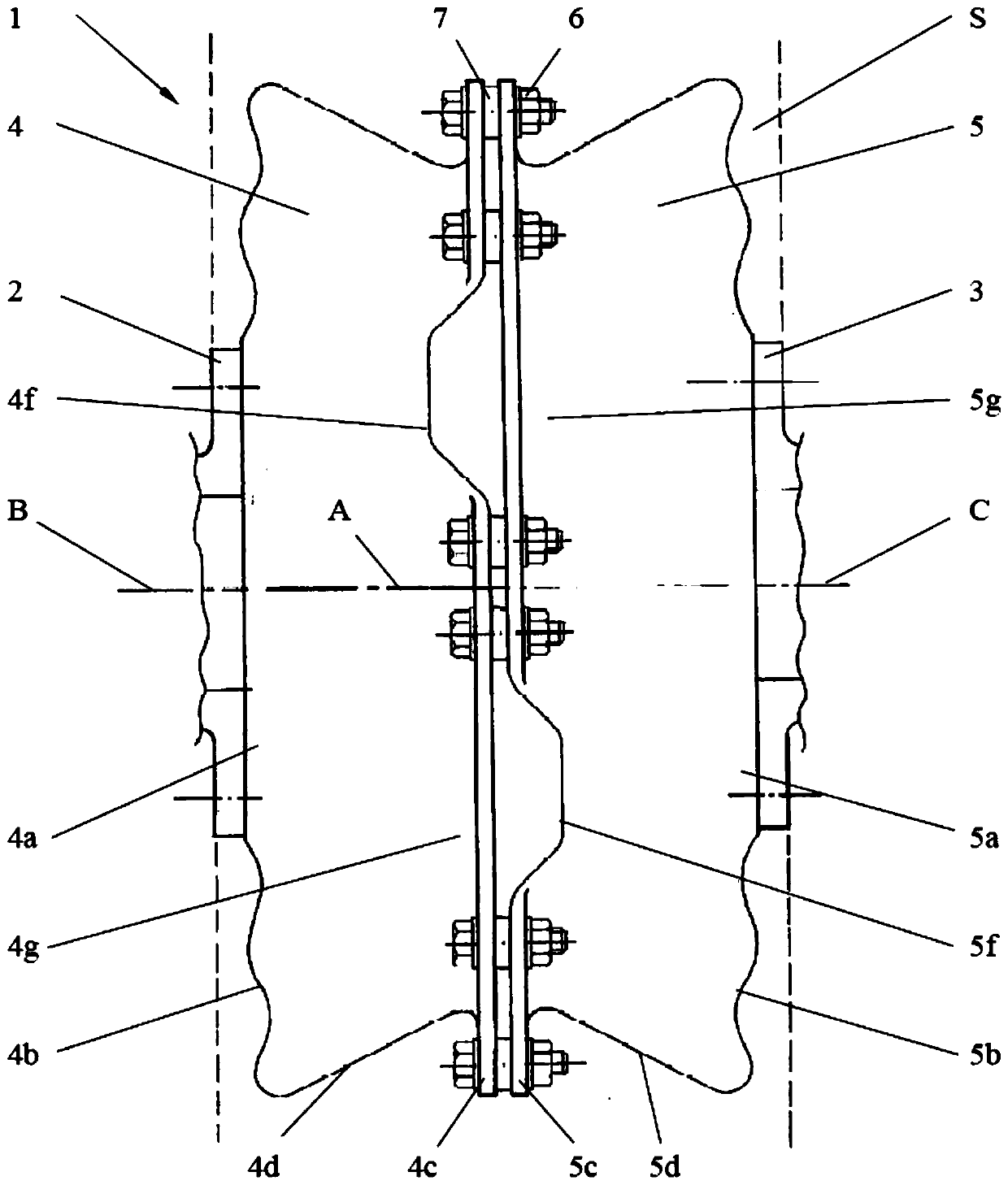
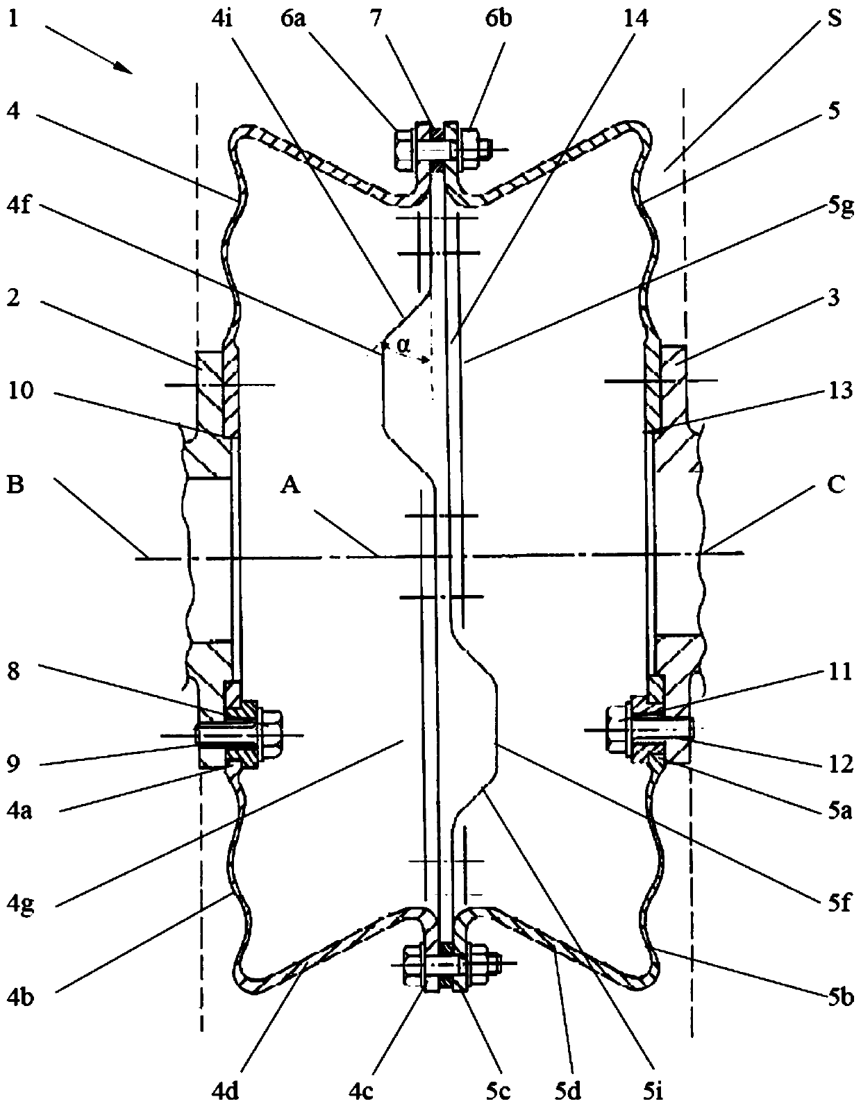
[0029] This embodiment shows the shaft coupling 1 arranged in the transmission system, and the coupling 1 is configured to connect the first transmission element 2 (drive element) and the second transmission element 3 (drive element) of the transmission system , to compensate the angular displacement, axial displacement and radial displacement between transmission elements 2 and 3. The transmission elements 2 and 3 can be arranged in the form of flanges as shown, but can also have other shapes.

[0030] figure 1 The dotted lines shown delimit the extent of the installation space S between the supporting structures of the transmission elements 2 and 3 , which can be, for example, part of the housing of the engine and gearbox of a ship. The coupling 1 can also be provided in a transmission system for other purposes. Essentially, for the purposes of the inven...


PUM


Abstract

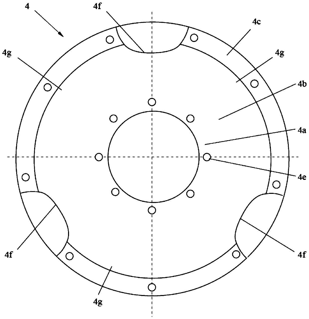
The coupling includes a first connecting member, a second connecting member and a connecting element connecting the first and the second connecting member. Each connecting member is made of a single piece of synthetic material, has a first flange portion connecting one of the drive elements, a partition portion extending radially outward from the first flange portion, a second flange portion, and a partition portion extending radially outward from the partition. The outer periphery of the plate part extends to the tubular structure part of the second flange part. Each tubular structure portion has two or more recesses, the recesses being separated from each other by non-recesses in the circumferential direction. In the first relative position of the first and second connecting members, the concave portion of the first connecting member faces the concave portion of the second connecting member to form a hole capable of entering the inside of the coupling. In the second relative position, which is the coupling operation mode, the recesses of the first and second connecting members are deviated in the circumferential direction and face the non-recesses respectively. Couplings provide high compensation forces, high bending safety and torsional rigidity without reducing the transmitted torque or increasing consumables.

Description

technical field [0001] The invention relates to the field of displacement compensating couplings made of fiber composite materials. [0002] In particular, the invention relates to a coupling comprising a first connecting member made of a single piece of synthetic material, and the first member has a first flange portion to which a first drive element is connected, along the length of the first flange portion a diaphragm portion extending radially outward, a second flange portion, and a tubular structure portion extending from the periphery of the diaphragm portion to the second flange portion, a second connecting member made of a monolithic synthetic material, and the second The connecting member has a first flange portion connected to the second transmission element, a diaphragm portion extending outward in the radial direction of the first flange portion, a second flange portion, and a flange portion extending from the outer circumference of the diaphragm portion to the sec...

Claims


Application Information

Patent Timeline
Patent Type & Authority Patents(China)
IPC IPC(8): F16D3/72
CPCF16D3/72F16D3/725Y10T29/49877F16D3/74F16D2003/745F16D3/005F16D3/04F16D3/06
Inventor 马提亚·盖斯林格科尼利斯·盖斯林格安德烈亚斯·布兰兹塔特
Owner ELLERGON ANTRIEBSTECHN GMBH
Learn More