An integrated mechanism of manipulator and gripper
A manipulator and gripper technology, applied in the field of industrial robots, can solve the problems of increasing the quality of the end effector, affecting the positioning accuracy of the manipulator, complex structure of the gripper and must be arranged on the end effector of the manipulator, etc., to achieve lightweight , the effect of reducing weight
- Summary
- Abstract
- Description
- Claims
- Application Information
AI Technical Summary
Problems solved by technology
Method used
Image
Examples
Embodiment 1
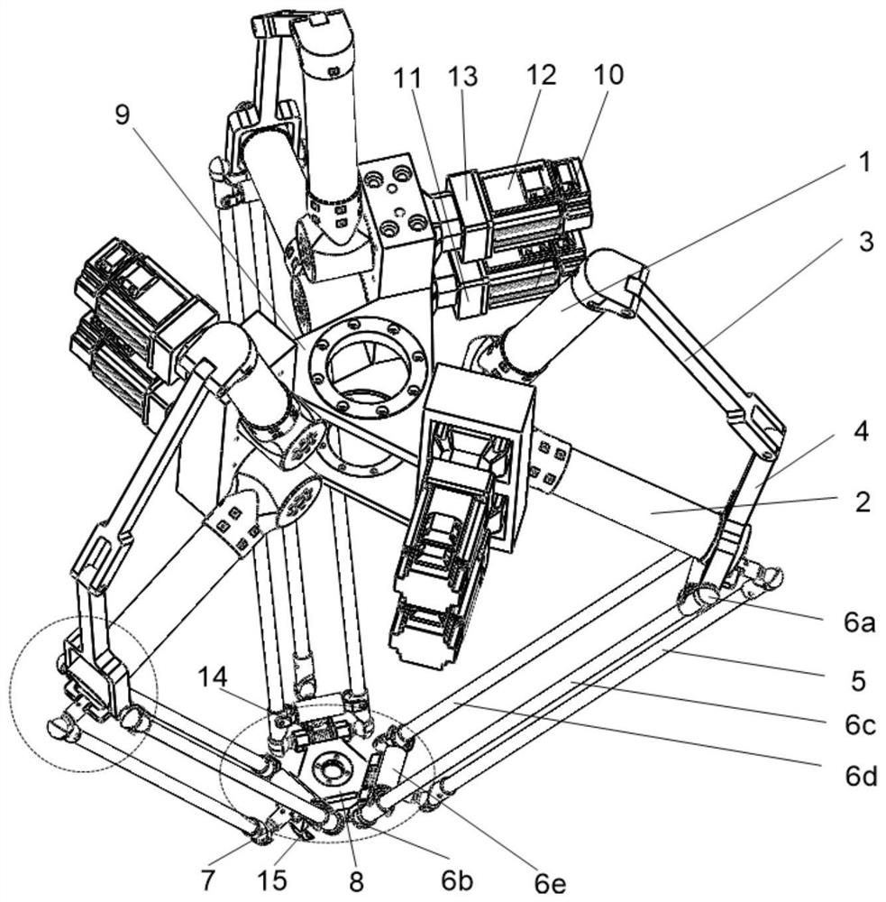
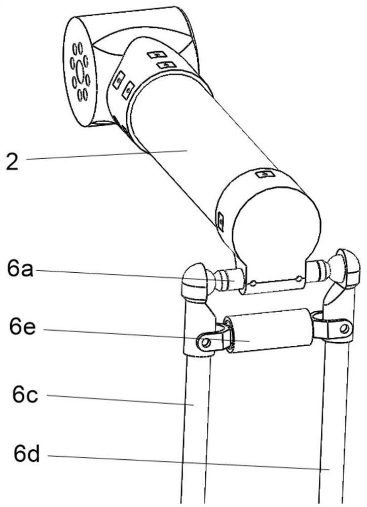
[0021] Such as figure 1 , figure 2 with image 3 As shown, a mechanism integrating a manipulator and a claw includes a fixed platform 9 and a moving platform 8, and three main drive branch chains connected in parallel between the fixed platform 9 and the moving platform 8; it is characterized in that it also includes setting The claw driving mechanism on the main drive branch chain, the claw 15 and the torsion spring 14 arranged on the moving platform 8;
[0022] The three main drive branch chains have the same structure, including drive motor 10, speed reducer 11, master arm 2 and slave arm assembly, and are connected in sequence; one end of the master arm 2 is connected to the fixed platform 9 through a rotating pair, and the other end It is connected with the driven arm assembly; the driven arm assembly is connected with the moving platform 8; the driving motor 10 and the speed reducer 11 are fixed on the fixed platform 9, and the driving motor 10 drives the main arm 2 t...
Embodiment 2
[0026] Such as Figure 4 with Figure 5 As shown, the difference between this embodiment and Embodiment 1 is that the three branch chains are fixed on the semicircle of the platform 9 at 90°; The drive motor 12 rotating shafts of the claw driving mechanism of the first branch chain and the driving motor 12 rotating shafts of the claw driving mechanism of the second branch chain are respectively arranged on the driving motor 10 rotating shaft of the main driving branch chain of the first branch chain, the second The top of the drive motor 10 rotating shaft of the main drive branch chain of the two branch chains; the number of the claw drive mechanism, the claw 15 and the torsion spring 14 arranged on the main drive branch chain is 2 sets, symmetrically arranged on the moving platform 8 both sides; the main drive branch chain and the claw drive mechanism are the same as in embodiment 1; the claws 15 and torsion spring 14 arranged on the moving platform 8 are the same as in embo...
Embodiment 3
[0028] Such as Image 6 , Figure 7 with Figure 8 As shown, the difference between this embodiment and Embodiment 2 is that one of the three branch chains is provided with a claw drive mechanism, and the drive motor 12 of the first branch chain is arranged on the second axis. Above the rotating shaft of the drive motor 10 of the main drive branch chain of a chain; the driven arm assembly adopts a plane 4R parallelogram mechanism, that is, the connecting rods 6c and 6d are connected with the connecting rods 6c and 6d through a rotating pair; The active arm 2 is connected with the upper link 6a through a rotary pair, and the axis of the rotary pair is parallel to the axis of the rotary pair where the active arm 2 is connected with the fixed platform 9; the lower link 6b is connected with the moving platform 8 through a rotary pair, the The axis of the rotating pair coincides with the axis of the lower connecting rod 6b; the arrangement of the three branch chains is the same a...
PUM
 Abstract
Description
Claims
Application Information
 - R&D Engineer
- R&D Manager
- IP Professional
- Industry Leading Data Capabilities
- Powerful AI technology
- Patent DNA Extraction
Browse by: Latest US Patents, China's latest patents, Technical Efficacy Thesaurus, Application Domain, Technology Topic, Popular Technical Reports.
© 2024 PatSnap. All rights reserved.Legal|Privacy policy|Modern Slavery Act Transparency Statement|Sitemap|About US| Contact US: help@patsnap.com


