
Planar antenna folding bracket

A technology of plate antenna and folding bracket, which is applied in the direction of folding antenna and radiating element structure

Active Publication Date: 2020-02-18
SOUTHWEST JIAOTONG UNIV
View PDF16 Cites 2 Cited by
  • Summary
  • Abstract
  • Description
  • Claims
  • Application Information

AI Technical Summary

Problems solved by technology

[0004] The purpose of the present invention is to provide a plate antenna folding bracket, which can effectively solve the problem of portability of the plate antenna

Method used


Image

  • Planar antenna folding bracket
  • Planar antenna folding bracket
  • Planar antenna folding bracket

Examples


Embodiment Construction

[0021] The present invention will be further described in detail below in conjunction with the accompanying drawings and specific embodiments.

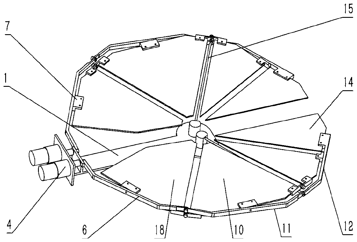
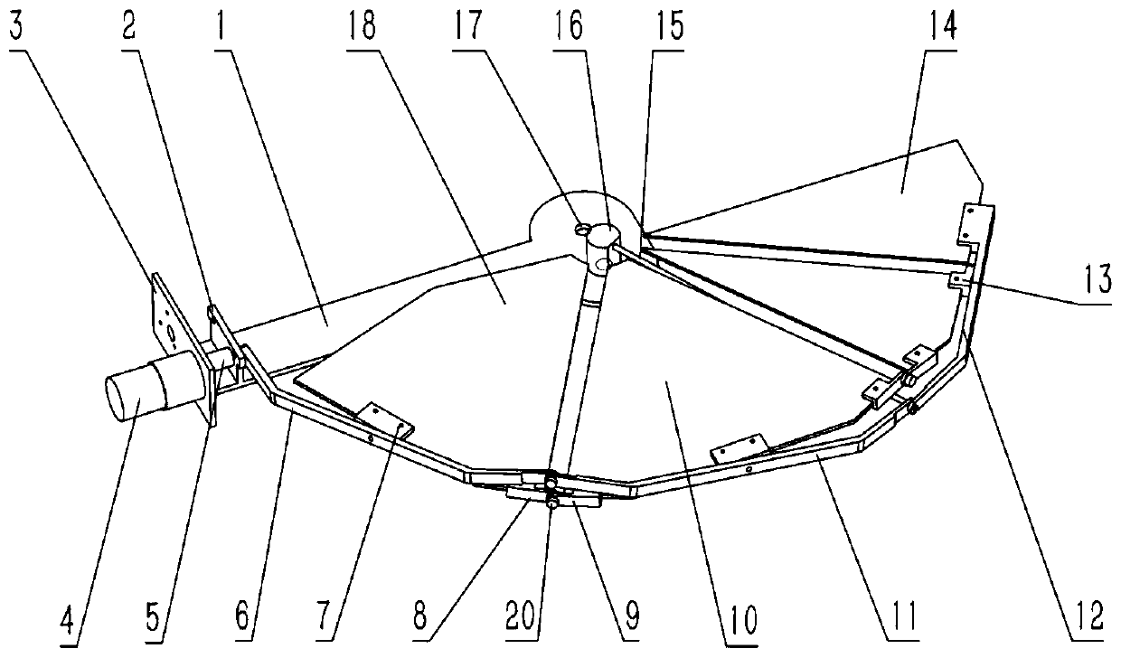
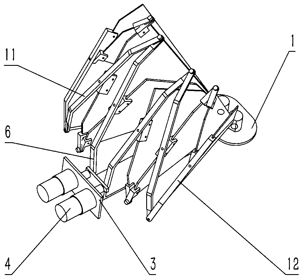
[0022] A folding support for a plate-shaped antenna, comprising a base 1, a geared motor 4, a coupling 5, and a plate-shaped antenna and a hinge. The base 1 has a plate-type motor base 3 and a connecting rod support 2, and the geared motor 4 is fixed on the plate-type motor base 3 by screws; the plate-shaped antenna, connecting rods and several hinges form a three-stage scissor structure, and the first-stage scissors The fork is made of: the first connecting rod 6, the first plate support 7, the first plate antenna 18 and the left half hinge 8; the second stage scissors is made of: the right half hinge 9, the second plate antenna 10, the first The plate support 7, the second connecting rod 11 and the left hinge 8 are composed; the third stage scissors are composed of: the third connecting rod 12, the third plate antenna 14, the right ...


PUM


Abstract

The invention provides a planar antenna folding bracket and belongs to the technical field of mechanism design. A base is a long plate structure. Through-holes are disposed on both sides of an elliptical disk in the long-axis direction. A link support is arranged in parallel with a tail planar motor base. The output shaft of a reduction motor passes through a shaft hole and is connected with the right-angle shaft of the first link through a coupling. The first link is a rectangular bar member folded inwards twice and has a front end hinged to the tail end of a second link. The front end of thesecond link is hinged to the tail end of a third link. The rotation shaft of a first plate support is hinged to the through hole on the middle section of the first link. The outer arc edge of a fan-like first planar antenna is fixedly connected to the first plate support. A left half hinge is arranged on a junction of the right straight edge of the first planar antenna and the arc edge. A right half hinge is arranged on a junction of the left straight edge of the second planar antenna and the arc edge. The third link is a structure folded inwards once and has a front end provided with a fixedsecond plate support. The tail end of the third link and the front end of the second link are hinged through the end portion of a support rod.

Description

technical field [0001] The invention belongs to the technical field of mechanism design. Background technique [0002] Although most areas in the world now have strong signal coverage, it is more difficult to receive satellite signals in sparsely populated areas such as deserts, snow-capped mountains, and virgin forests. People trapped in these areas are less likely to successfully seek help from the outside world through communication devices such as mobile phones. If a plate antenna is used to receive signals, this can greatly increase the possibility of rescue. The plate antenna has the advantages of high gain, good sector pattern, small rear lobe, reliable sealing performance and long service life, and is widely used for outdoor signal propagation. [0003] There are a lot of researches on the plate antenna, most of them use electrical and control methods to enhance the performance of the antenna or other issues, but none of them involve enhancing the receiving performa...

Claims


Application Information

Patent Timeline
IPC IPC(8): H01Q1/08H01Q1/36
CPCH01Q1/08H01Q1/36Y02E10/50
Inventor 张祖涛郭亮潘亚嘉袁艳平
Owner SOUTHWEST JIAOTONG UNIV
Learn More