
Screw barrel component for injection molding machine

A technology for the screw and barrel of an injection molding machine, applied in the field of screw and barrel components of an injection molding machine, which can solve the problems of low heat energy and poor polymer melting state, and achieve the effects of high work efficiency, convenient extrusion of materials, and enhanced sealing

Pending Publication Date: 2020-02-18
ZHEJIANG OCEAN UNIV DONGHAI SCI & TECH COLLEGE
View PDF0 Cites 1 Cited by
  • Summary
  • Abstract
  • Description
  • Claims
  • Application Information

AI Technical Summary

Problems solved by technology

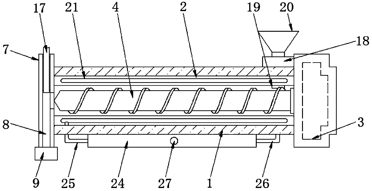
[0005] Aiming at the deficiencies of the prior art, the present invention provides a screw barrel assembly for an injection molding machine, which solves the problem that the existing screw barrel assembly of an injection molding machine can only perform one injection in one working cycle, and the screw barrel assembly adopts a single screw structure , the heat energy generated is small, and the polymer melting state is poor

Method used


Image

  • Screw barrel component for injection molding machine
  • Screw barrel component for injection molding machine
  • Screw barrel component for injection molding machine

Examples


Embodiment Construction

[0030] The technical solutions in the embodiments of the present invention will be clearly and completely described below with reference to the accompanying drawings in the embodiments of the present invention. Obviously, the described embodiments are only a part of the embodiments of the present invention, but not all of the embodiments. Based on the embodiments of the present invention, all other embodiments obtained by those of ordinary skill in the art without creative efforts shall fall within the protection scope of the present invention.

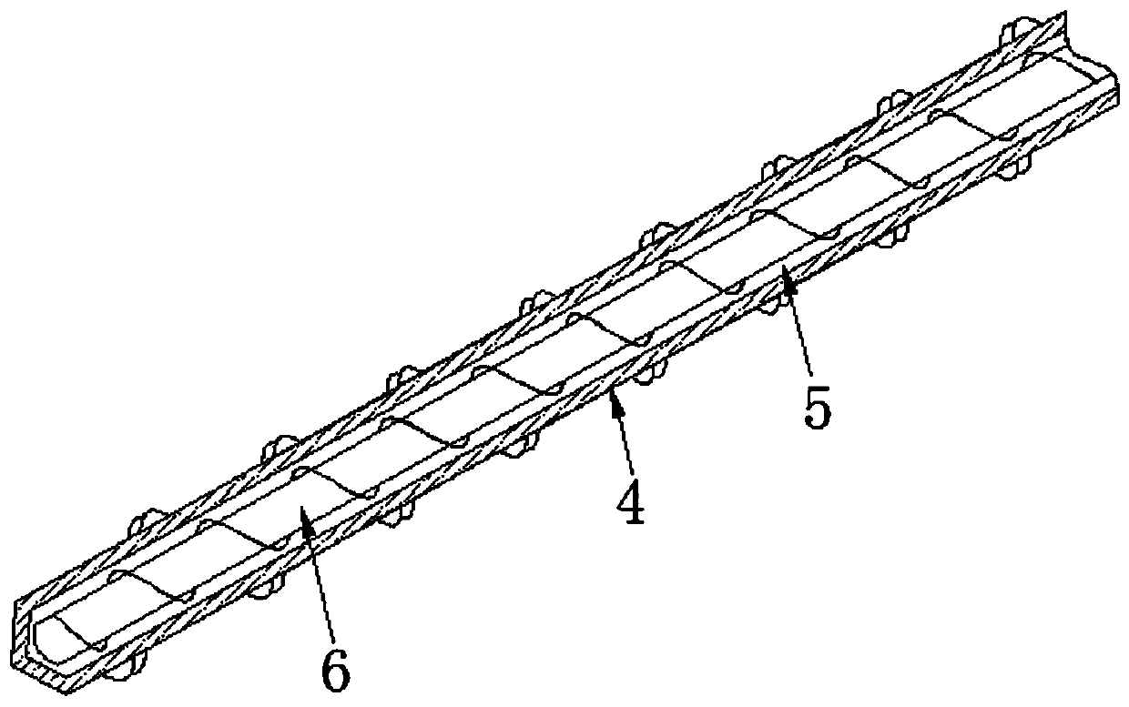
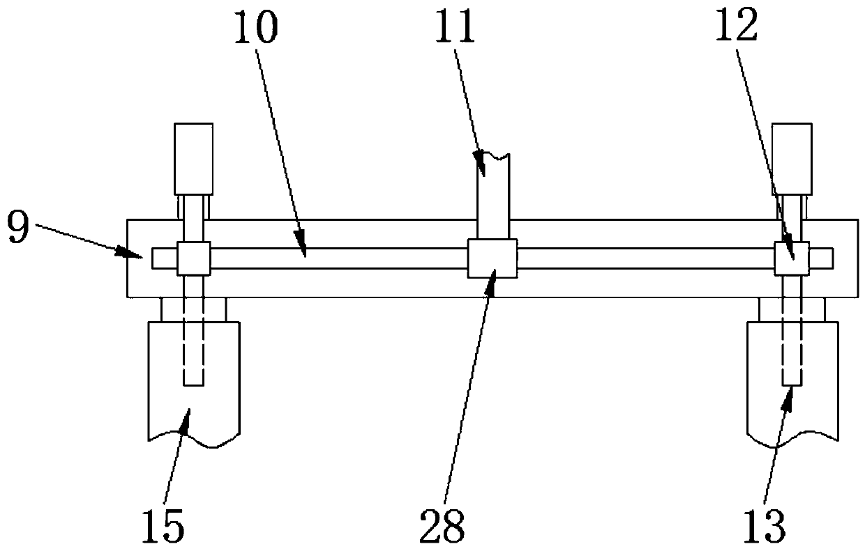
[0031] see Figure 1-6, the embodiment of the present invention provides a technical solution: a screw and barrel assembly of an injection molding machine, including a barrel 1, a water tank 24 is fixedly connected to the bottom of the barrel 1, and a water inlet pipe 25 is connected to the left side of the water tank 24, and the water tank 24 The right side is communicated with a water outlet pipe 26, one end of the water inlet pipe ...


PUM


Abstract

The invention discloses a screw barrel component for an injection molding machine. The screw barrel component comprises a barrel, and the inner wall of the barrel is fixedly connected with a barrel bushing; and the inner right side of the barrel is fixedly connected with a driving device, and the barrel bushing is internally provided with an outer screw rod. The invention relates to the technicalfield of injection molding machines. According to the screw barrel component for the injection molding machine, through arrangement an inner screw rod in the outer screw rod, the inner screw rod absorbs heat for providing heat energy to the outer screw rod and improving the rotating force of the outer screw rod, so that tremendous internal friction heat generated by interface shear, of polymers atthe clearance position between the barrel bushing and the outer screw rod is increased; quick and efficient fusion of the polymers is achieved, and then one side of a feed chute communicates with oneside of a fine groove through rotation of a cylindrical rod in a cylindrical pipe; since a material separation mechanism is arranged, the waiting time of the injection molding machine can be shortened effectively; and the working efficiency of the injection molding machine can be improved greatly, and the energy consumption is reduced.

Description

technical field [0001] The invention relates to the technical field of injection molding machines, in particular to a screw and barrel assembly of an injection molding machine. Background technique [0002] Plastic machines are also known as injection molding machines or injection molding machines. It is the main molding equipment for making thermoplastics or thermosetting plastics into various shapes of plastic products using plastic molding dies. Divided into vertical, horizontal, all-electric. The injection molding machine heats the plastic, applying high pressure to the molten plastic so that it is ejected to fill the mold cavity. The working principle of the injection molding machine is similar to that of a syringe for injection. It uses the thrust of the screw (or plunger) to inject the plasticized plastic in the molten state (that is, the viscous state) into the closed mold cavity. The process of obtaining products after curing and shaping. Injection molding is a ...

Claims


Application Information

Patent Timeline
Patent Type & Authority Applications(China)
IPC IPC(8): B29C45/47B29C45/60B29C45/62B29C45/74
CPCB29C45/47B29C45/60B29C45/62B29C45/74
Inventor 王骁徐东闫海强
Owner ZHEJIANG OCEAN UNIV DONGHAI SCI & TECH COLLEGE
Learn More