
Positioning device of fork ear type thin-wall part

A technology of positioning device and thin-walled parts, which is applied in the direction of positioning device, metal processing mechanical parts, clamping, etc., can solve the problems of difficult processing of fork lug thin-walled parts, and achieves the improvement of processing efficiency and processing accuracy, as well as improving processing efficiency. , to avoid the effect of deformation

Active Publication Date: 2020-02-18
AECC AVIATION POWER CO LTD
View PDF5 Cites 2 Cited by
  • Summary
  • Abstract
  • Description
  • Claims
  • Application Information

AI Technical Summary

Problems solved by technology

[0003] Aiming at the problem of difficult processing of fork ear-shaped thin-walled parts in the prior art, the present invention provides a positioning device for fork-ear-shaped thin-walled parts, which solves the problem that it is difficult to ensure the machining accuracy when drilling fork-ear-shaped thin-walled parts, and improves Improve the machining efficiency and machining accuracy of fork ear parts

Method used


Image

  • Positioning device of fork ear type thin-wall part
  • Positioning device of fork ear type thin-wall part
  • Positioning device of fork ear type thin-wall part

Examples


Embodiment Construction

[0037] The present invention will be further described in detail below in conjunction with the accompanying drawings, which are explanations rather than limitations of the present invention.

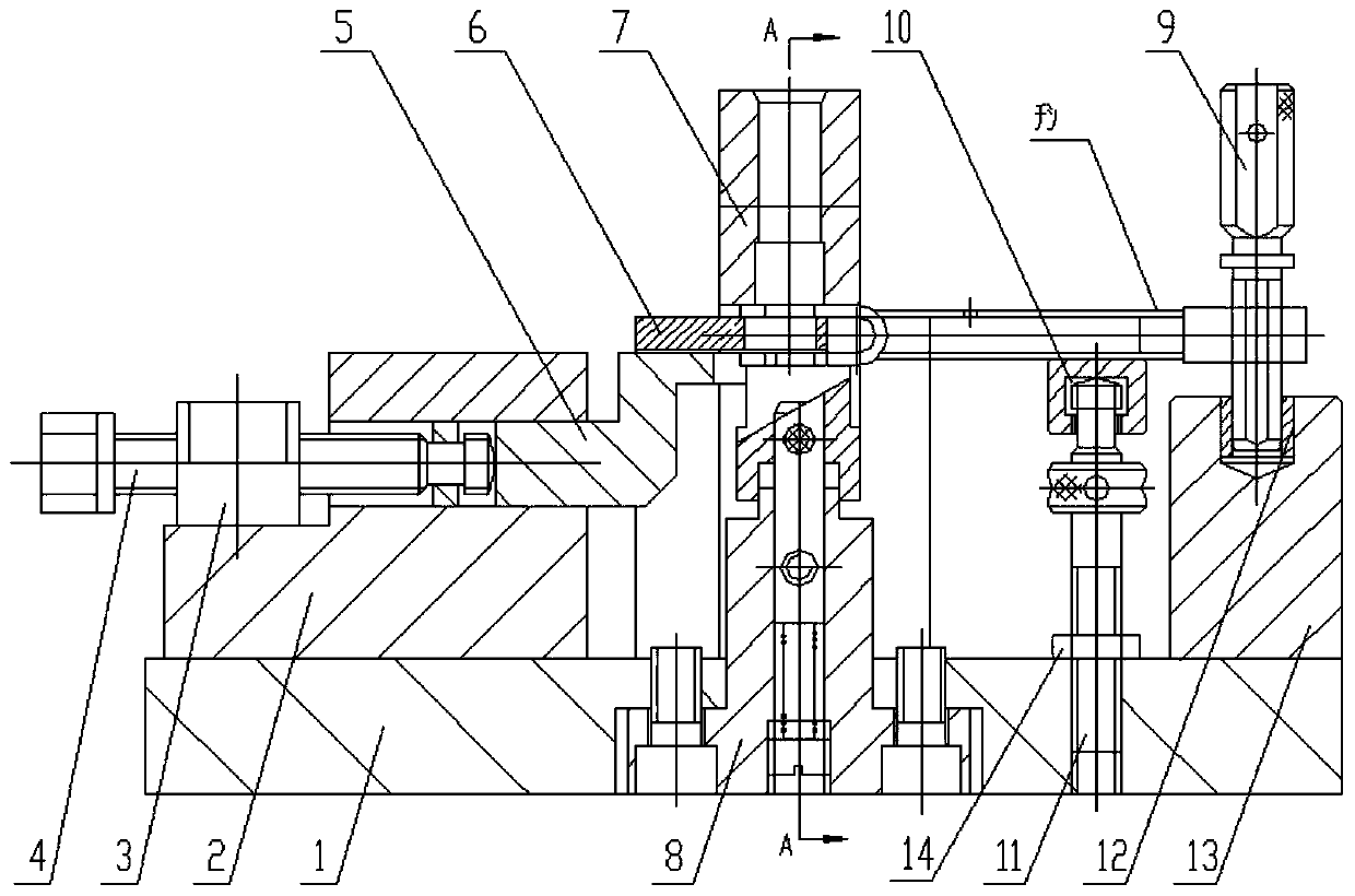
[0038] refer to Figure 2-8 , a positioning device for fork ear type thin-walled parts, including a base plate 1, and a guide block 2, a positioning seat 6, a base 13 and a guide template 7 arranged on the base plate, the guide block 2 and the base 13 are located on the base plate 1 The positioning seat 6 is located between the guide block 2 and the base 13 at both ends.

[0039] The positioning seat 6 is a U-shaped structure, including two vertical support arms and a positioning arm horizontally arranged on the top of the two support arms. The U-shaped groove is clamped on the positioning wall, and the other end of the fork-shaped thin-walled part is fixedly arranged on the top of the base 13, and the positioning wall and the base can make the fork-shaped thin-walled part in a horizont...


PUM


Abstract

The invention discloses a positioning device of a fork ear type thin-wall part. The positioning device comprises a bottom plate, a positioning seat, a guide template and a telescopic supporting frame.A fork ear of the to-be-machined part is inserted into a positioning wall. The telescopic supporting frame is arranged between two supporting arms of the positioning seat, and the top of the telescopic supporting frame abuts against the bottom face of the lower side wall of the fork ear. The guide template is arranged on the top of the positioning seat and arranged on the upper side wall of the fork ear in a press-fit manner, a drill bit guide hole is formed in the guide template, and a drill rod penetrates through the drill bit guide hole to machine the two side walls of the fork ear. According to the device, the two side walls of the fork ear are supported by the supporting arms and the telescopic supporting frame separately, the problem that the to-be-machined part deforms due to the pressure of the drill bit in the machining process is avoided, the machining precision of the fork ear type thin-wall part is guaranteed, and the machining efficiency is improved.

Description

technical field [0001] The invention relates to the machining technology of thin-walled parts, in particular to a positioning device for fork ear type thin-walled parts. Background technique [0002] Three fork-shaped thin-walled parts in the rotor assembly of an aero-engine, one end of which is a U-shaped thin-walled part (see figure 1 ), the thickness is only 2mm, and it is required to drill through holes (diameter is 10mm) on the double-layer thin-walled parts. L1 is divided into three groups, the wall is thin and the difference between the two is only 0.7mm. However, due to the high requirement for the coaxiality of the upper and lower holes of the part (0.02mm), the position of the processing hole has a high requirement for symmetry in the width of the part. Since it is a thin-walled part, it is easy to change the shape during processing, and it is difficult to meet the processing requirements. Contents of the invention [0003] Aiming at the problem of difficult pro...

Claims


Application Information

Patent Timeline
IPC IPC(8): B23B41/00B23Q3/06
CPCB23B41/00B23Q3/065
Inventor 黄洪展张小莉陶彩玲秦瑾琦王荣王素娟胡婷婷牛伟栋
Owner AECC AVIATION POWER CO LTD
Learn More