New energy automobile battery damping and cooling device and battery temperature adjusting device
A technology for new energy vehicles and cooling devices, applied in battery/fuel cell control devices, batteries, electric vehicles, etc., can solve the problems of temperature rise, affecting the performance and service life of batteries of new energy vehicles, and heat generated by batteries. The effect of service life
- Summary
- Abstract
- Description
- Claims
- Application Information
AI Technical Summary
Problems solved by technology
Method used
Image
Examples
Embodiment 1
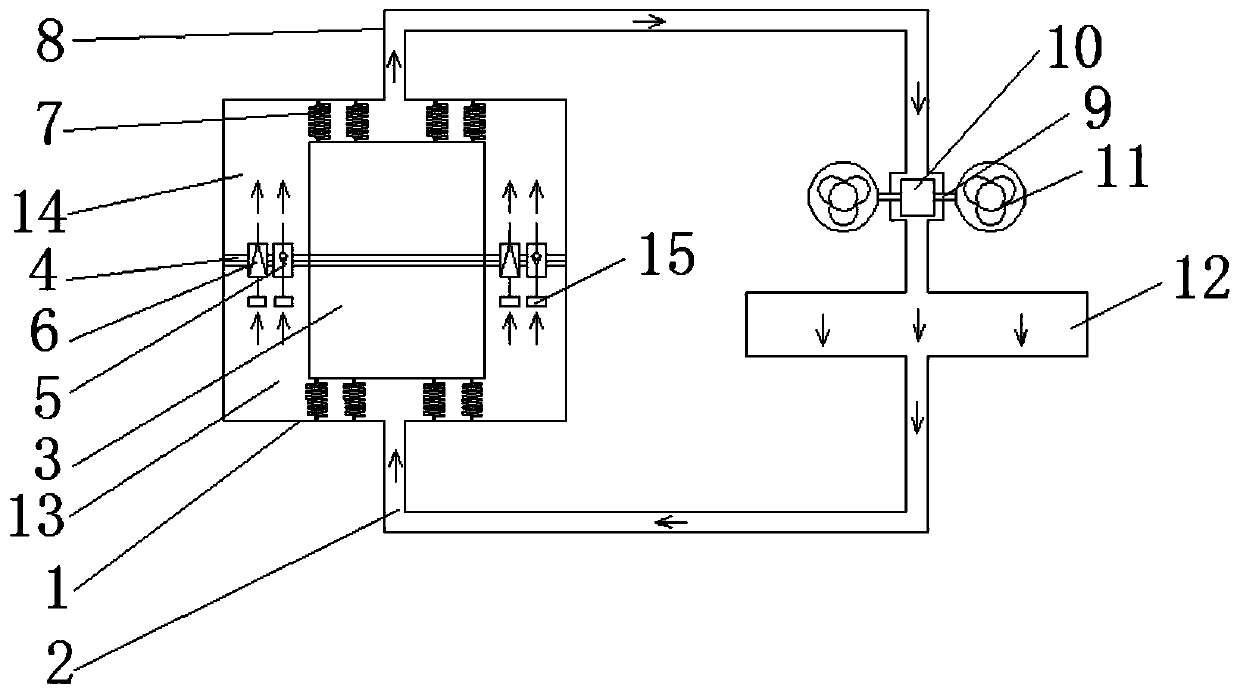
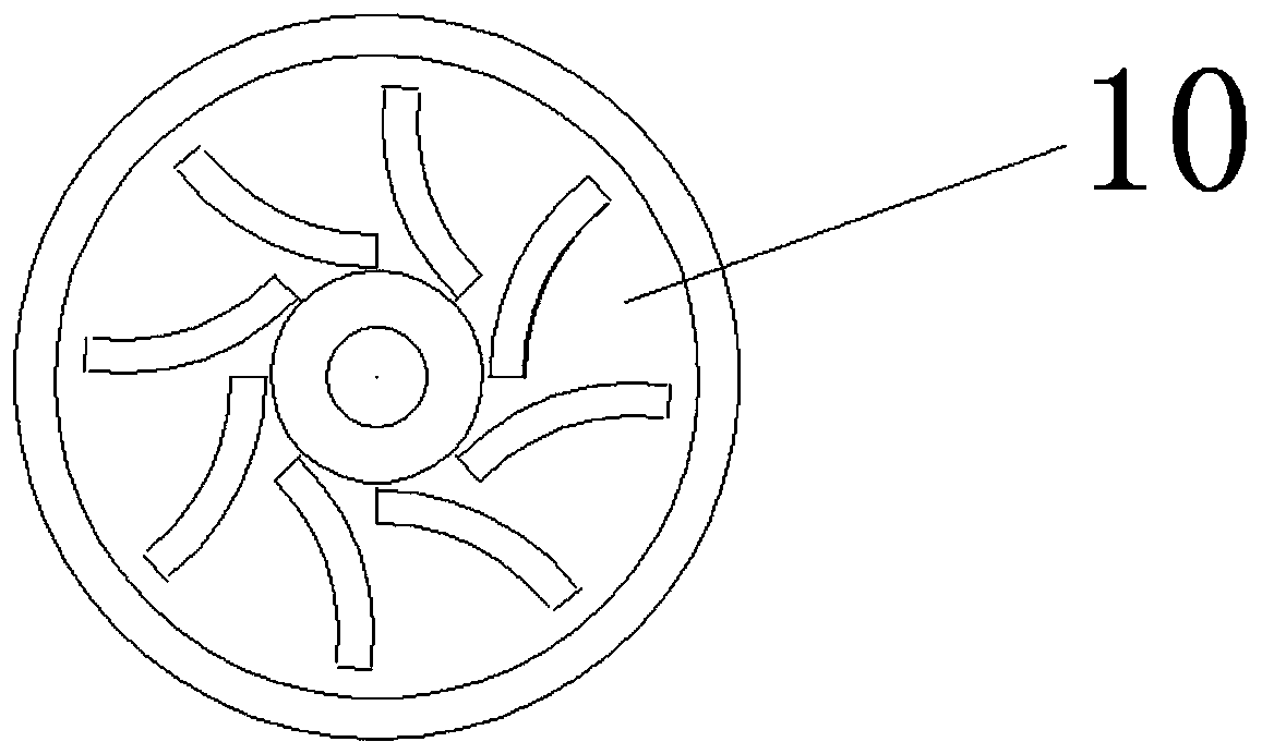
[0030] Embodiment 1: as figure 1 As shown, a new energy vehicle battery shock absorbing cooling device of the present invention includes a sealed coolant tank 1, a cooling pipeline 8 connected to the inlet and outlet of the coolant tank 1, and a radiator 12 connected to the cooling pipeline 8, and the battery 3 is placed in the sealed coolant tank 1, and a separator 4 is sealed and installed in the coolant tank 1. The separator 4 is sealed and connected with the battery 3, and moves with the battery 3. The one-way valve 6 and the pressure relief valve 5 for the coolant 2 on both sides of the separator 4 are provided with elastic connectors 7 between the two ends of the battery 3 and the coolant tank 1 along the direction of liquid flow; when the car is running, the battery 3 vibrates , the coolant 2 is extruded in the coolant tank 1 to flow in one direction, circulates along the cooling pipeline 8, and flows back into the coolant tank 1 after being dissipated by the radiator 1...
Embodiment 2
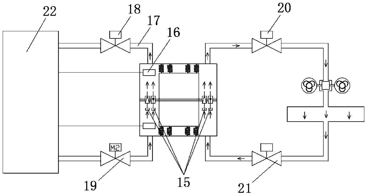
[0042] Embodiment 2: as figure 2As shown, the difference between this example and Example 1 is that in order to adapt to the use in cold regions in winter, this example is a new energy vehicle battery temperature regulating device, including the new energy vehicle battery shock absorbing cooling device and heating temperature described in Example 1. The control device, the temperature control device includes a temperature control pipeline 17, a temperature detection and a heater 16, and the temperature control pipeline 17 is respectively connected to the coolant tank 1 of the shock absorption cooling device and the new energy vehicle control system 22 Above, a closed loop is formed. An electric valve I18 and an electric valve II19 are installed on the temperature control pipeline 17. One end of the temperature detection and heater 16 is connected to the new energy vehicle control system 22, and the other end is set in the coolant tank 1 to detect the cooling temperature. The ...
Embodiment 3
[0048] Embodiment 3: This example is a temperature control device for a new energy vehicle battery, including a sealed coolant tank 1, a temperature control pipeline 17, a temperature detection and a heater 16, and the battery 3 is placed in the sealed coolant tank 1 In the coolant tank 1, a separator 4 is sealed and installed. The separator 4 is sealed and connected with the battery 3, and moves with the battery 3. A one-way valve connected to the coolant on both sides of the separator 4 is connected to the separator 4. 6 and a pressure relief valve 5, elastic connectors 7 are provided between the two ends of the battery 3 along the liquid flow direction and the coolant tank 1; the temperature control pipelines 17 are respectively connected to the coolant tank 1 of the cooling device and the new On the energy vehicle control system 22, a closed loop is formed. One end of the temperature detection and heater 16 is connected to the new energy vehicle control system 22, and the o...
PUM
 Abstract
Description
Claims
Application Information
 - R&D
- Intellectual Property
- Life Sciences
- Materials
- Tech Scout
- Unparalleled Data Quality
- Higher Quality Content
- 60% Fewer Hallucinations
Browse by: Latest US Patents, China's latest patents, Technical Efficacy Thesaurus, Application Domain, Technology Topic, Popular Technical Reports.
© 2025 PatSnap. All rights reserved.Legal|Privacy policy|Modern Slavery Act Transparency Statement|Sitemap|About US| Contact US: help@patsnap.com


