
SC type polarization maintaining optical fiber connector

A polarization-maintaining optical fiber and connector technology, applied in light guides, optics, instruments, etc., can solve the problems of cumbersome operation, difficult disassembly and reuse, poor tensile and aging resistance, etc., to achieve increased tensile resistance, tensile and anti-aging Good performance and increased service life

Pending Publication Date: 2020-02-14
OFT OPTOELECTRONICS TECH
View PDF0 Cites 2 Cited by
  • Summary
  • Abstract
  • Description
  • Claims
  • Application Information

AI Technical Summary

Problems solved by technology

[0002] Polarization-maintaining optical fiber transmits linearly polarized light, which is widely used in various fields of national economy such as aerospace, aviation, navigation, industrial manufacturing technology and communication. In the interferometric optical fiber sensor based on optical coherent detection, the use of polarization-maintaining optical fiber can guarantee The direction is unchanged, and the coherent signal-to-noise ratio is improved to achieve high-precision measurement of physical quantities. The existing SC optical fiber active connector consists of a tail sleeve, a spinning clamping ring, a spring seat, a spring, an inner bush, an outer bush and Composed of ceramic ferrule, the inner bushing and spring seat form a whole by buckling, and the ceramic ferrule and spring are fixed in the inner space, the spinning clamping ring is formed into a whole by crimping and spring seat, and the optical fiber is formed by glue and Spinning clamping rings are fixed together, the whole structure is cumbersome to operate, the effectiveness of the fixing method between the optical fiber and the parts is completely determined by the nature of the glue, its tensile and aging resistance is poor, and the whole structure is not easy to disassemble and reuse

Method used


Image

  • SC type polarization maintaining optical fiber connector
  • SC type polarization maintaining optical fiber connector
  • SC type polarization maintaining optical fiber connector

Examples


Embodiment Construction

[0023] The following will clearly and completely describe the technical solutions in the embodiments of the present invention with reference to the accompanying drawings in the embodiments of the present invention. Obviously, the described embodiments are only some, not all, embodiments of the present invention. Based on the embodiments of the present invention, all other embodiments obtained by persons of ordinary skill in the art without making creative efforts belong to the protection scope of the present invention.

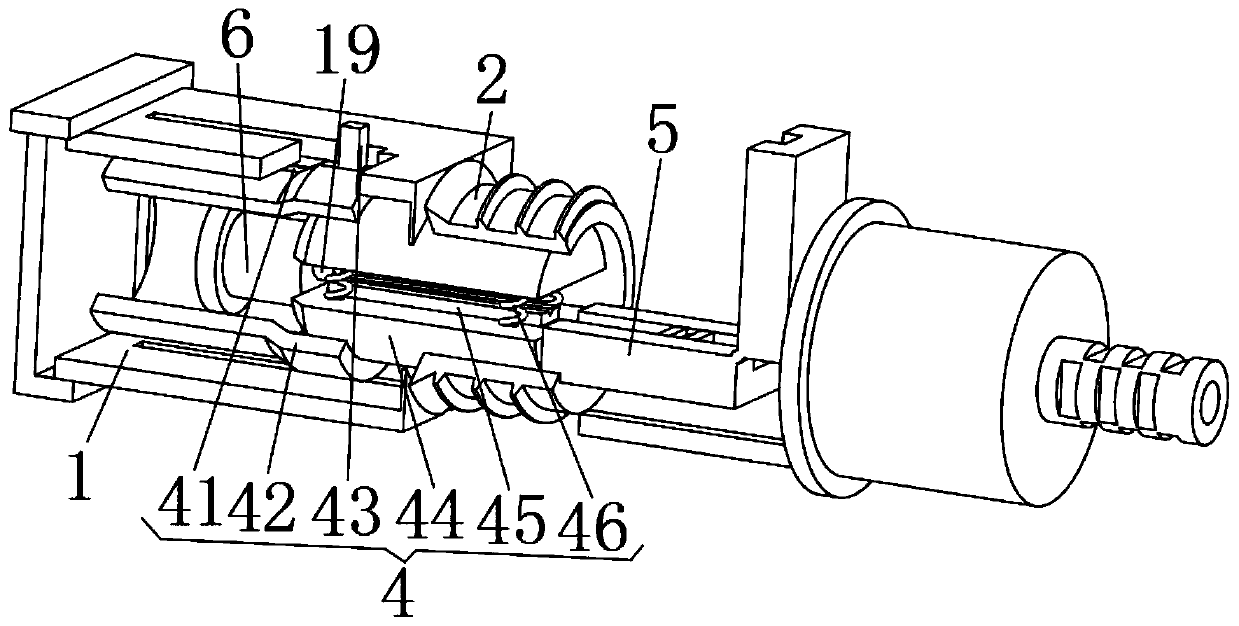
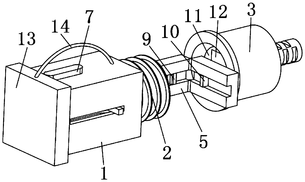
[0024] see Figure 1-3 , the present invention provides a technical solution: an SC type polarization maintaining optical fiber connector, including a housing 1 and a fixing unit 4;

[0025] Shell 1: the inside of the shell 1 is hollow, the right end of the shell 1 is fixedly connected with the left end of the threaded joint 2, and the threaded joint 2 is threaded with the tailstock 3;

[0026] Fixed unit 4: The fixed unit 4 includes a limit groove 41, a fixe...


PUM


Abstract

The invention discloses an SC type polarization maintaining optical fiber connector. The SC type polarization maintaining optical fiber connector comprises a shell and a fixing unit. The internal portion of the shell is hollow, the right end of the shell is fixedly connected with the left end of a threaded connector, and the threaded connector is in threaded connection with a tailstock; the fixingunit comprises limiting grooves, a fixing cylinder, limiting rods, clamping plates, a rubber pad and springs, the side of the right end of the fixing cylinder is fixedly connected with the inner sideof the shell, the side of the fixing cylinder is provided with two limiting grooves which penetrate the side of the shell, there are two clamping plates, the sides of the left ends of the two clamping plates are provided with limiting rods, the two limiting rods are slidingly connected with the two limiting grooves, springs are respectively arranged at the four corners of the upper surface of theclamping plate at the lower side, the upper ends of the four springs are fixedly connected with the four corners of the lower surface of the clamping plate at the upper side. The SC type polarizationmaintaining optical fiber connector can conveniently and rapidly fix the optical fiber in the connector, is good in tensile and can be conveniently detached and reused.

Description

technical field [0001] The invention relates to the technical field of optical fiber communication, in particular to an SC type polarization maintaining optical fiber connector. Background technique [0002] Polarization-maintaining optical fiber transmits linearly polarized light, which is widely used in various fields of national economy such as aerospace, aviation, navigation, industrial manufacturing technology and communication. In the interferometric optical fiber sensor based on optical coherent detection, the use of polarization-maintaining optical fiber can guarantee The direction is unchanged, and the coherent signal-to-noise ratio is improved to achieve high-precision measurement of physical quantities. The existing SC optical fiber active connector consists of a tail sleeve, a spinning clamping ring, a spring seat, a spring, an inner bush, an outer bush and Composed of ceramic ferrule, the inner bushing and spring seat form a whole by buckling, and the ceramic fe...

Claims


Application Information

Patent Timeline
IPC IPC(8): G02B6/38
CPCG02B6/3812G02B6/3821G02B6/3837G02B6/3881
Inventor 周永军
Owner OFT OPTOELECTRONICS TECH
Learn More