
Geophysical prospecting continuously controllable seismic source device

A technology of seismic sources and air intake pipes, which is applied in measuring devices, seismology, geophysical measurements, etc., can solve the problems of fast gas source consumption, weak airflow energy excitation intensity, long inflation time, etc., and achieve the effect of improving efficiency

Pending Publication Date: 2020-02-14
HUIZHOU UNIV
View PDF1 Cites 0 Cited by
  • Summary
  • Abstract
  • Description
  • Claims
  • Application Information

AI Technical Summary

Problems solved by technology

This kind of seismic source uses the airflow energy of the gas combustion explosion directly as the source energy to excite the excitation point. The excitation intensity of the airflow energy is relatively weak, easy, and the excitation effect is not good, and multiple excitations may be required.
In addition, the emission energy of the seismic source is adjusted by controlling the inflation time, but since the volume of the detonator is fixed, its adjustment range must be limited, and when small energy emission is required, in order to obtain the mixed gas density of small energy, it is necessary to The amount of gas inflated is large, causing the gas source to be consumed quickly, and the inflation time is also long, and the work efficiency is low

Method used


Image

  • Geophysical prospecting continuously controllable seismic source device
  • Geophysical prospecting continuously controllable seismic source device
  • Geophysical prospecting continuously controllable seismic source device

Examples


Embodiment Construction

[0025] The following will clearly and completely describe the technical solutions in the embodiments of the present invention with reference to the accompanying drawings in the embodiments of the present invention. Obviously, the described embodiments are only some, not all, embodiments of the present invention. Based on the embodiments of the present invention, all other embodiments obtained by persons of ordinary skill in the art without making creative efforts belong to the protection scope of the present invention.

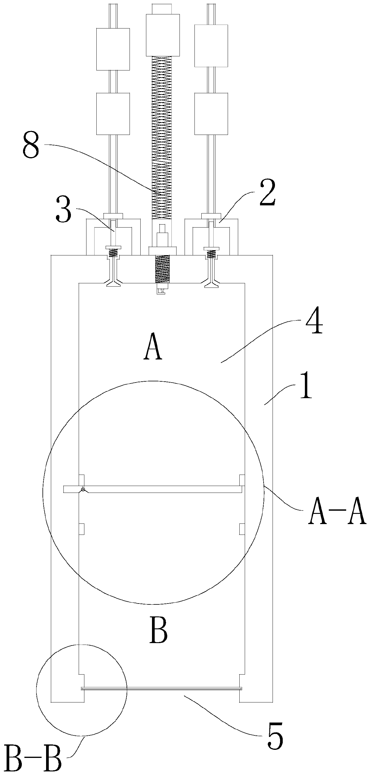
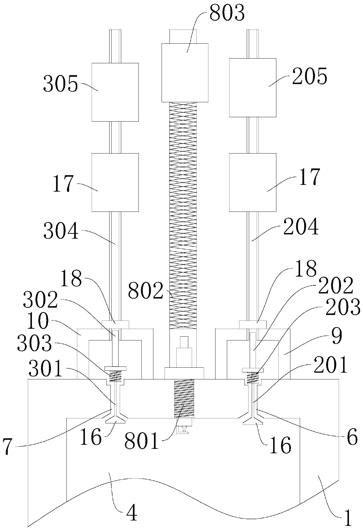
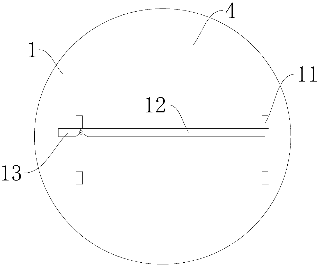
[0026] see Figure 1 to Figure 4 , the present invention provides the following technical solutions:

[0027] A continuously controllable seismic source device for geophysical prospecting, comprising:

[0028] The shock tube main body 1 is in the shape of a rectangle as a whole, has a rectangular cavity 4 inside, and has a rectangular opening 5 communicating with the rectangular cavity 4 at its tail end. The front wall of the shock tube main body 1 is provide...


PUM


Abstract

The invention discloses a geophysical prospecting continuously controllable seismic source device. Oxygen is input through a first gas inlet pipe and fuel gas is input through a second gas inlet pipeat intervals of a period of time, the oxygen and the fuel gas are mixed in a combustion area according to a certain proportion, an electric spark plug performs timing automatic interval ignition, explosion occurs in a combustion chamber at intervals of a period of time, when mixed gas is excited to explode, high-temperature and high-pressure gas is formed, the high-temperature and high-pressure gas is transmitted in a shock tube body, an isolation door body is instantaneously rotated to be attached to the side wall of a rectangular cavity under the traction of a reset spring hinge to form shock waves, so that the shock tube body vibrates, when the mixed gas in the shock tube body is burnt out, the isolation door body is reset under the traction of the reset spring hinge, and then the nextgas enters the mixed ignition shock waves, so that a seismic source capable of stably emitting vibration waves is formed. According to the invention, the efficiency of converting the sound wave energyis improved through the shock tube main body, the seismic source excitation is sustainable, and the excitation interval time, the energy intensity and the excitation frequency can be controlled.

Description

technical field [0001] The invention belongs to the technical field of geophysical exploration, and in particular relates to a continuously controllable seismic source device for geophysical exploration. Background technique [0002] At present, the seismic sources used for acoustic exploration in geological exploration can be divided into two types: explosive sources and non-explosive sources. Among them, the energy generated by explosive sources such as explosives and shaped energy bombs is large, but most of the energy is scattered in the air environment, and the divergence is not stable. It is concentrated and has certain risks and uncontrollability. Each filling takes a lot of time, and has the disadvantages of low efficiency and low resource utilization. Non-explosive sources can be divided into pulse sources and vibrators. Common pulse sources include electric sparks, air guns, vibrating hammers, etc. Electric sparks and vibrating hammers only have one pulse each time...

Claims


Application Information

Patent Timeline
Patent Type & Authority Applications(China)
IPC IPC(8): G01V1/137
CPCG01V1/137
Inventor 戴学军张玉静吴娇
Owner HUIZHOU UNIV
Learn More