Eureka AIR delivers breakthrough ideas for toughest innovation challenges, trusted by R&D personnel around the world.

Thermal power plant flue gas recirculation and sludge drying coupled on-line mixed-burning system

A technology of flue gas recirculation and sludge drying, which is applied in the directions of sludge treatment, water/sludge/sewage treatment, dehydration/drying/thickened sludge treatment, etc. It can solve the problems affecting dust and sulfur discharge and system operation Insufficient flexibility, excessive boiler discharge and other problems, to achieve the effect of reducing the oxygen content of the boiler, flexible system operation mode, and lightening the load

Pending Publication Date: 2020-02-14
山西平朔煤矸石发电有限责任公司
View PDF0 Cites 4 Cited by
  • Summary
  • Abstract
  • Description
  • Claims
  • Application Information

AI Technical Summary

Problems solved by technology

[0005] In order to solve the leakage of malodorous gas in the current sludge drying mixed combustion system, the toxic and harmful organic substances in the flue gas cause environmental pollution and affect the discharge of dust and sulfur, the system operation is not flexible enough, and the boiler NO at low load x To solve the technical problem of excessive emissions, the present invention provides a thermal power plant flue gas recirculation coupling sludge drying online blending system

Method used


Image

  • Thermal power plant flue gas recirculation and sludge drying coupled on-line mixed-burning system

Examples


Embodiment Construction

[0024] The present invention will be further described in detail with reference to the accompanying drawings and embodiments.

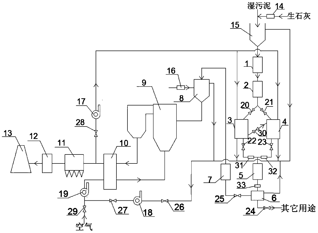
[0025] Such as figure 1As shown, the thermal power plant flue gas recirculation coupling sludge drying online blending system in this embodiment includes a circulating fluidized bed power generation system and a sludge drying system, wherein: the circulating fluidized bed power generation system includes Weighing coal feeder 16, dosing bin 8, boiler 9, air preheater 10, dust collector 11, desulfurization tower 12, chimney 13 and third fan 19, weighing coal feeder 16, dosing bin 8, boiler 9 , air preheater 10, deduster 11, desulfurization tower 12 and chimney 13 are connected successively by pipeline, the inlet of the 3rd fan 19 is connected with air source, the outlet of the 3rd fan 19 is connected with the air side inlet of air preheater 10; The sludge drying system includes a quicklime weighing conveyor 14, a wet sludge bin 15, a first screw convey...


PUM


Abstract

The invention provides a thermal power plant flue gas recirculation and sludge drying coupled on-line mixed-burning system, and belongs to the field of boiler flue gas waste heat utilization and sludge drying in order to solve the problems that in a current system, odorous gas leaks, flue gas carries toxic and harmful organic matter, consequently, environmental pollution is caused, and up-to-standard discharge of dust and sulfur is affected, system operation is not flexible enough, boiler NOx emission exceeds the standard during the low load. After a quick lime weighing conveyor in a sludge drying system mixes wet sludge with quick lime, a mixture is conveyed into one or two drying machines through a first screw conveyor and a sludge strip cutting machine, 120-150 DEG C high-temperature flue gas from a circulating fluidized bed power generation system enters the drying machines to be dried, dried sludge is conveyed into a blending bin through a dried sludge weighing conveyor to be mixed with pulverized coal and then enters a boiler for burning, flue gas from the drying machines serves as boiler primary air for recirculation to be delivered back to a hearth, the circulating fluidized bed power generation system is combined with the sludge drying system, and after the wet sludge is dried through flue gas waste heat, the dried sludge is taken as fuel for burning power generation.

Description

technical field [0001] The invention relates to the technical field of waste heat utilization of boiler flue gas in a thermal power plant and sludge drying utilization, and in particular relates to an on-line co-combustion system for thermal power plant flue gas recirculation coupled with sludge drying. Background technique [0002] In recent years, environmental protection requirements have become more and more stringent, especially for sewage treatment. With the increasing scale of sewage treatment plants, sludge production is also increasing. Sludge has the characteristics of high water content and huge volume, which is extremely inconvenient in the process of storage, transportation, loading and unloading, etc., and there are also high potential environmental safety risks and hidden dangers. Reduction and recycling are imperative. At present, sludge treatment methods mainly include landfill, composting, natural drying or incineration. Practice has shown that sludge dry...

Claims


Application Information

Patent Timeline
IPC IPC(8): C02F11/145C02F11/13C02F11/00F23G7/00
CPCC02F11/145C02F11/13C02F11/00F23G7/001
Inventor 张润元乔岗杰刘红刚王亚琴赵云凯骆丁玲延彪武建芳石龙龙赵耀芳何利昌尉万红廖光明周银行李光
Owner 山西平朔煤矸石发电有限责任公司
Why Eureka
Eureka Blog
Learn More