
Guide wire feeding device for computer wire-stripping machine

A wire feeding device and wire stripping machine technology, which is applied to circuits, electrical components, transportation and packaging, etc., can solve the problems of inability to flexibly adjust the use height of the guiding wire feeding device, increase the friction force of the wire, and reduce the flexibility, so as to avoid The effect of wasting wire material, increasing equipment life and improving flexibility

Pending Publication Date: 2020-02-14
芜湖瑞昌电气系统有限公司
View PDF1 Cites 4 Cited by
  • Summary
  • Abstract
  • Description
  • Claims
  • Application Information

AI Technical Summary

Problems solved by technology

[0004] The existing guide wire feeding device for computer wire stripping machine has certain disadvantages in the process of use. The traditional guide wire feeding device for computer wire stripping machine adopts a frictional moving structure to guide the wire body, which increases the friction of the wire. During the production process, the wire and the wire rod will be worn out, and the wire will be stuck during the wire feeding process; at the same time, the guide wire feeding device for the traditional computer wire stripping machine does not have a moving adjustment structure, so that it cannot flexibly adjust the guide wire feeding The use height of the device reduces its flexibility in use; secondly, the guide wire feeding device of the traditional computer wire stripping machine adopts a bolt-type fixed structure for installation and fixing operation, which increases the difficulty of operation during installation and brings certain problems to users. Adverse effects of

Method used


Image

  • Guide wire feeding device for computer wire-stripping machine
  • Guide wire feeding device for computer wire-stripping machine
  • Guide wire feeding device for computer wire-stripping machine

Examples


Embodiment Construction

[0027] The technical solutions in the embodiments of the present invention will be clearly and completely described below in conjunction with the embodiments of the present invention. Apparently, the described embodiments are only some of the embodiments of the present invention, not all of them. Based on the embodiments of the present invention, all other embodiments obtained by persons of ordinary skill in the art without creative efforts fall within the protection scope of the present invention.

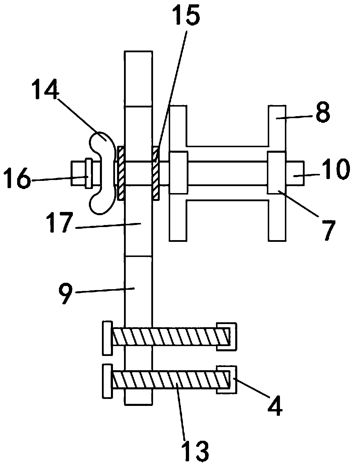
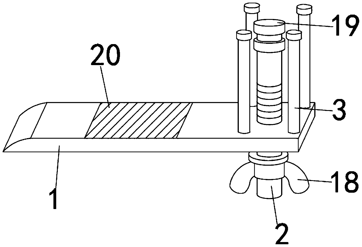
[0028] Such as Figure 1-4 As shown, a guide wire feeding device for a computer wire stripping machine includes a fixed base 5, a docking clamp 1 and a guide wheel 8, the guide wheel 8 is movably installed on the upper part of the fixed base 5, and the outer surface of the rear end of the fixed base 5 The fixed side plate 9 is fixedly installed, and the fixed base 5 is docked and fixed by the fixed side plate 9 and the guide wheel 8. The inner middle position of the guide wheel 8 ...


PUM


Abstract

The invention discloses a guide wire feeding device for a computer wire-stripping machine. The guide wire feeding device comprises a fixed base, a butt joint clamping plate and a guide wheel. The guide wheel is movably mounted on the upper portion of the fixed base. A fixed side plate is fixedly mounted on the outer surface of the rear end of the fixed base. The fixed base is in butt joint with the guide wheel and is fixed to the guide wheel through the fixed side plate. The middle of the inner side of the guide wheel is connected with a connecting rod in a sleeving manner, and the outer surface of the connecting rod is movably sleeved with two sets of bearings. The guide wheel and the connecting rod are movably connected through the bearings. The guide wheel and the fixed side plate are in butt joint and are fixed through the connecting rod. A fixed clamping ring is fixedly mounted on the side, close to the fixed side plate, of the outer surface of the connecting rod. According to theguide wire feeding device for the computer wire-stripping machine, sliding motion replaces traditional friction motion, contact of a guide wire and a guide hole can be effectively avoided, and the service life of equipment is prolonged; and wire raw material waste is avoided, the guide wire feeding device is provided with an adjusting structure, and the use flexibility of the guide wire feeding device is improved.

Description

technical field [0001] The invention belongs to the technical field of guide wire feeding devices, in particular to a guide wire feeding device for a computer wire stripping machine. Background technique [0002] The guide wire feeding device for the computer wire stripping machine is a kind of guide wire feeding device for assisting the wire feeding operation of the computer wire stripping machine during the stripping process of the computer wire stripping machine. The guide wire feeding device can be used Adjust the feeding direction of the wire to reduce the wear of the wire during wire feeding. [0003] The comparative document CN202997288U discloses a computer wire stripping machine with a two-way bending device, including a chassis, on which a display screen, buttons, switches, pressure tension knobs, lifting wheel knobs and pressure adjustment knobs are arranged. The front panel of the wire stripping machine is equipped with a lead plate, a positioning frame, a guidi...

Claims


Application Information

Patent Timeline
IPC IPC(8): B65H57/14B65H57/06H01R43/28
CPCB65H57/06B65H57/14H01R43/28
Inventor 郭俞吕小宝
Owner 芜湖瑞昌电气系统有限公司
Learn More