Thread milling device for screw

A wire milling and equipment technology, applied in metal processing equipment, maintenance and safety accessories, thread cutting machines, etc., can solve the problems of manual operation and high time cost, and achieve the effect of preventing self-falling and convenient cleaning

Active Publication Date: 2020-02-14
SICC CO LTD
View PDF8 Cites 0 Cited by
  • Summary
  • Abstract
  • Description
  • Claims
  • Application Information

AI Technical Summary

Problems solved by technology

[0006] In order to solve the above-mentioned problems in the prior art, that is, to solve the problem that manual operation is required for the cleaning of the existing screw, resulting in high time costs, the present disclosure provides a thread milling device for a screw, which includes The body and the linear drive device, rotary drive device, sleeve, sleeve cover, milling device and fixing device arranged on the body; the fixing device is used to fix the target screw; the milling device is used to clean the The target screw, and the milling device is arranged inside the sleeve; the linear drive device is used to drive one of the fixing device and the sleeve to move axially, so that the fixing device Relatively moving with the thread milling device; the rotary driving device is used to drive at least one of the fixing device and the sleeve to rotate, so that the fixing device and the thread milling device are relatively rotated; the The radial section of the inner space of the sleeve gradually becomes larger toward the direction of the fixing device; the sleeve cover is provided with a through hole allowing the target screw to pass through, and the sleeve cover and the sleeve One end close to the fixture is detachably connected together

Method used


Image

  • Thread milling device for screw
  • Thread milling device for screw
  • Thread milling device for screw

Examples


no. 1 example

[0036] The first embodiment of the present disclosure is specifically as follows:

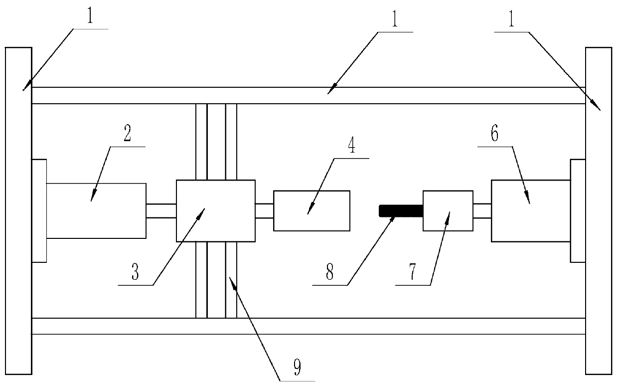
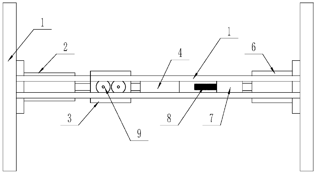
[0037] Such as figure 1 and 2 As shown, in the first embodiment of the present disclosure, the milling equipment for screw mainly includes a machine body 1, an electric push rod 2 as a linear drive device, a first motor 3 as a rotary drive device, a sleeve 4, a milling A wire device 5, a second motor 6 as a rotary drive device and a fixing device 7. Wherein, the casing (not marked in the figure) of electric push rod 2 is connected with figure 1 The left end of the middle body 1 is fixedly connected, the push rod (not shown in the figure) of the electric push rod 2 is fixedly connected with the shell of the first motor 3, the rotating shaft of the first motor 3 is fixedly connected with the sleeve 4 coaxially, and the thread milling device 5 is fixedly installed in the sleeve 4. The housing (not shown in the figure) of the second motor 6 and figure 1 The right end of the middle body 1 is fi...

no. 2 example

[0052] The second embodiment of the present disclosure is specifically as follows:

[0053] Such as Figures 6 to 11 As shown, the difference between the second embodiment and the first embodiment is only the structure of the sleeve 4, and the second embodiment also adds a sleeve cover 11 on the basis of the first embodiment. For the convenience of description, only the differences between the second embodiment and the first embodiment will be described in detail below, and no corresponding description will be given for the similarities between the second embodiment and the first embodiment.

[0054] Such as Figure 6 to Figure 8 As shown, the sleeve 4 is a tapered sleeve, and the end of the sleeve 4 with a smaller diameter is fixedly connected to the rotating shaft of the first motor 3, and the end of the sleeve 4 with a larger diameter is detachably connected with the sleeve cover 5 . Those skilled in the art can understand that the connection between the sleeve 4 and the...

no. 3 example

[0058] The third embodiment of the present disclosure is specifically as follows:

[0059] Such as Figure 12 with 13 As shown, the only difference between the third embodiment and the second embodiment is that a brush 12 is added on the basis of the second embodiment. For the convenience of description, only the differences between the third embodiment and the second embodiment will be described in detail below, and no corresponding description will be given for the similarities between the third embodiment and the second embodiment.

[0060] Such as Figure 12 As shown, the brush 12 mainly includes a brush body 121 and bristles 122 . Wherein, the brush body 121 has a ring structure, and the bristles 122 are evenly arranged on the inner circumferential surface of the brush body 121 .

[0061] Such as Figure 13 As shown, the brush 12 is arranged inside the sleeve 4 and between the thread milling device 5 and the sleeve cover 11 . Those skilled in the art can understand ...


PUM


Abstract

The invention provides a thread milling device for a screw. The thread milling device for the screw comprises a machine body, and further comprises a linear drive device, a rotary drive device, a sleeve, a thread milling device and a fixing device which are arranged on the machine body, wherein the fixing device is used for fixing the target screw, the thread milling device is used for cleaning the target screw, the thread milling device is arranged on the inner side of the sleeve, the linear drive device is used for driving one of the fixing device and the sleeve to move in the axial direction so as to enable the fixing device and the thread milling device to perform relative motion, and the rotary drive device is used for the driving at least one of the fixing device and the sleeve to rotate so as to enable the fixing device and the thread milling device to perform relative rotation. The thread milling device for the screw can automatically complete cleaning for the target screw, meanwhile can further collect iron chippings which fall off from the thread milling device in cleaning through the sleeve, and prevents the iron chippings from falling to the ground. Accordingly, the thread milling device for the screw reduces involved manpower, saves time of workers, and reduces time cost.

Description

technical field [0001] The disclosure belongs to the field of screw rod processing equipment, and specifically provides a thread milling device for screw rods. Background technique [0002] In the process of production, transportation and use, the screw is often impacted by external force and bumped, which leads to the deformation of the external thread on the screw. The deformed screw is difficult to assemble with the nut. In order to ensure the normal use of the screw, it is necessary to deal with the deformed external thread. [0003] The technical means that often adopts at present is, by screwing the thread milling device with internal thread on the screw rod, the internal thread of thread milling device cuts off and cleans the deformed part of external thread. Wherein, the hardness and strength of the thread portion on the thread milling device are better than those on the screw rod, otherwise the thread milling device is easily damaged by the screw rod. [0004] It ...

Claims


Application Information

Patent Timeline
Patent Type & Authority Applications(China)
IPC IPC(8): B23G1/32B23Q11/00
CPCB23G1/32B23Q11/0053
Inventor 李帅赵建国李乃庆李鹏邱兴鲁陈龙徐殿翔
Owner SICC CO LTD
Why Eureka
Try Eureka