Auxiliary feeding and discharging device of numerical control synchronous bending machine

A bending machine and material unloading technology, applied in the field of bending machines, can solve the problems of uneven force, affecting the working environment, and moving the workpiece is not convenient and fast, so as to achieve uniform force, avoid excessive tension, take and Place convenient and quick effects

Inactive Publication Date: 2020-02-14
九江职院产教融合发展有限公司
View PDF0 Cites 3 Cited by
  • Summary
  • Abstract
  • Description
  • Claims
  • Application Information

AI Technical Summary

Problems solved by technology

[0003] However, when the bending machine bends a long and thin workpiece, the workpiece is bent in a segmented bending manner, and the bent workpiece needs to be positioned and moved during each bending process. The workpiece is not convenient and fast enough. Pulling the workpiece directly will easily cause scraps to scratch the workpiece, and it is not convenient to quickly place the workpiece on the bending machine after hoisting the workpiece with the lifting component, and it is easy to cause uneven force, so that the workpiece with a long length can be processed Bending occurs after forming, and it is not convenient to quickly clean up the scraps on the bent workpiece. During the bending process, it is easy to cause scraps to fly up, affecting the indoor working environment

Method used


Image

  • Auxiliary feeding and discharging device of numerical control synchronous bending machine
  • Auxiliary feeding and discharging device of numerical control synchronous bending machine
  • Auxiliary feeding and discharging device of numerical control synchronous bending machine

Examples


Embodiment Construction

[0026] In order to make the technical means, creative features, goals and effects achieved by the present invention easy to understand, the present invention will be further described below in conjunction with specific embodiments.

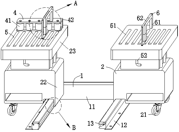
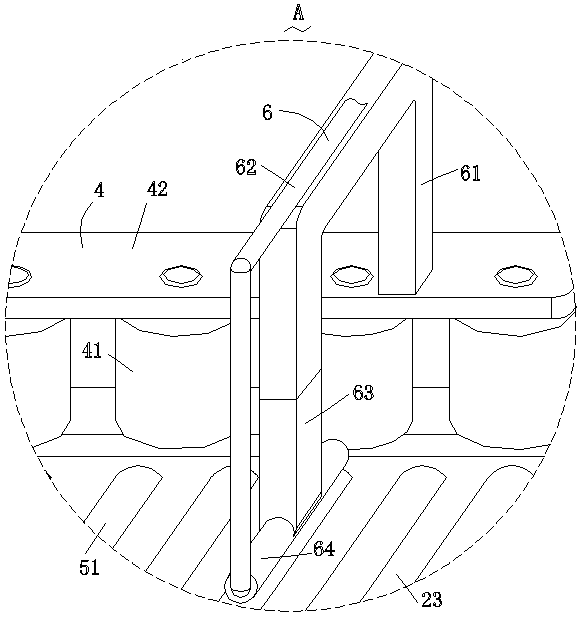
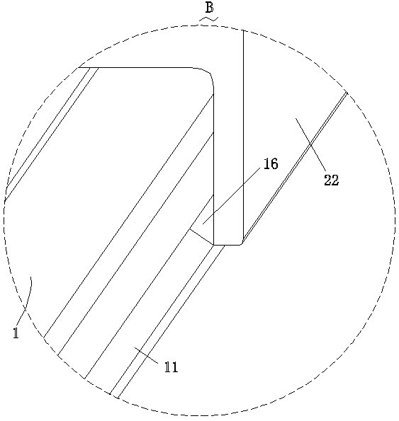
[0027] like Figure 1-Figure 8 As shown, an auxiliary loading and unloading device for a CNC synchronous bending machine according to the present invention includes a moving structure 1, a supporting structure 2, a motor 3, a first guiding structure 4, a second guiding structure 5 and a cleaning structure 6 The two ends of the mobile structure 1 are symmetrically provided with two support structures 2, which are used to adjust the distance between the support structure 2 and the horizontal direction of the bending machine between the mobile structure 1 and the support structure 2 Slidingly connected, and the motor 3 is arranged inside the moving structure 1; the end of the supporting structure 2 away from the moving structure 1 is provided with th...


PUM


Abstract

The invention relates to the field of bending machines, in particular to an auxiliary feeding and discharging device of a numerical control synchronous bending machine. The auxiliary feeding and discharging device of the numerical control synchronous bending machine comprises a moving structure, supporting structures, a motor, a first guide structure, second guide structures and cleaning structures. The moving structure and the supporting structures are connected in a sliding mode, and therefore the supporting structures are conveniently driven by the moving structure to change the position ofa workpiece, the supporting structures can be exposed, then the workpiece can be conveniently dismounted before the bending operation is conducted and after the bending operation is accomplished, meanwhile, the stress of the workpiece can be more uniform, and the phenomenon that due to the fact that the tension of the workpiece is overhigh, the workpiece is bent is effectively avoided. The secondguide structures are arranged at the ends, deviating from the moving structure, of the supporting structures, and therefore the workpiece on the supporting structures is conveniently moved, the workpiece position adjustment can be more convenient and faster, and the phenomenon that scratches are caused when the workpiece is moved is effectively avoided. The first guide structure is arranged on one supporting structure, and therefore the workpiece is conveniently located, the phenomenon that after the workpiece is moved, the workpiece needs to be located again is avoided, and then the bendingefficiency of the workpiece and the quality of the workpiece are greatly improved.

Description

technical field [0001] The invention relates to the field of bending machines, in particular to an auxiliary loading and unloading device for a numerically controlled synchronous bending machine. Background technique [0002] The bending machine is a machine capable of bending thin plates. Its structure mainly includes a bracket, a workbench and a clamping plate. The workbench is placed on the bracket. The workbench is composed of a base and a pressure plate. Connected, the base is composed of a seat shell, a coil and a cover plate. The coil is placed in the depression of the seat shell, and the top of the depression is covered with a cover plate. When in use, the coil is energized by a wire. Due to the use of electromagnetic force clamping for the clamping of thin plates, the pressing plate can be made into various workpiece requirements, and it can also process workpieces with side walls, and the operation is very simple. [0003] However, when the bending machine bends a...

Claims


Application Information

Patent Timeline
Patent Type & Authority Applications(China)
IPC IPC(8): B21D43/08B21D43/00B21D5/00B08B5/04
CPCB08B5/04B21D5/00B21D5/002B21D43/00B21D43/08
Inventor 陈永备陈丽君邵海军严春平
Owner 九江职院产教融合发展有限公司
Why Eureka
Try Eureka