Device based on rubber bladder forming with movable side pressure block and method of use thereof

A mobile, rubber bag technology, applied in the field of rubber bag forming, can solve the problems of poor anti-stabilization ability of suspended materials, increase of suspended parts of materials, insufficient inflow of sheet materials, etc., to facilitate the film attachment of parts and increase the distance , good forming effect

Active Publication Date: 2021-02-12
SHENYANG AEROSPACE UNIVERSITY
View PDF6 Cites 0 Cited by
  • Summary
  • Abstract
  • Description
  • Claims
  • Application Information

AI Technical Summary

Problems solved by technology

However, there are few researches on the design of side pressure block at present, and the parameter control is relatively difficult.
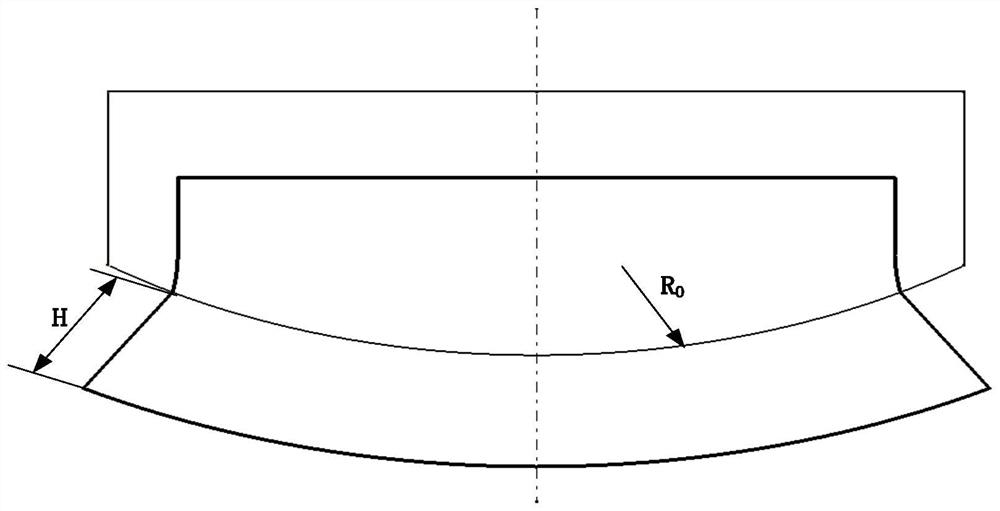
For example, the distance between the mold and the side press block and the amount of the edge of the sheet material on the side press block, if the distance is too small, the inflow of the sheet material will not be sufficient and the forming will not be possible; if the distance is too large, the suspended part of the material in the deformation zone will increase. Due to the poor anti-stabilization ability of suspended materials, wrinkling is more likely to occur; at the same time, too much overlap will increase the friction force on the sheet, so that the sheet is in danger of being pulled apart

Method used


Image

  • Device based on rubber bladder forming with movable side pressure block and method of use thereof
  • Device based on rubber bladder forming with movable side pressure block and method of use thereof
  • Device based on rubber bladder forming with movable side pressure block and method of use thereof

Examples


Embodiment Construction

[0035] In order to understand the above-mentioned purpose, features and advantages of the present invention more clearly, the present invention will be further described in detail below in conjunction with the accompanying drawings and specific embodiments. It should be noted that, in the case of no conflict, the embodiments of the present application and the features in the embodiments can be combined with each other.

[0036] In the following description, many specific details are set forth in order to fully understand the present invention. However, the present invention can also be implemented in other ways different from those described here. Therefore, the protection scope of the present invention is not limited by the specific details disclosed below. EXAMPLE LIMITATIONS.

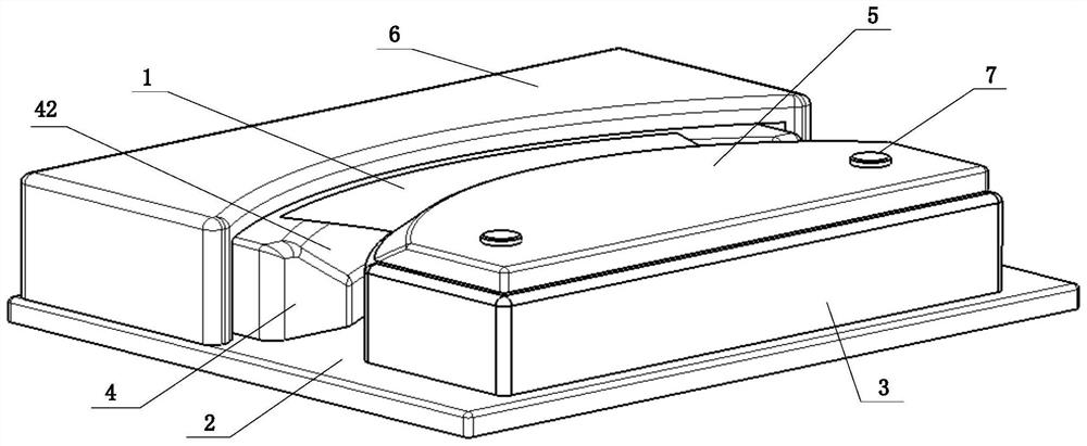
[0037] Refer below Figure 1 to Figure 8 The rubber bladder-based forming apparatus with movable side pressure blocks and methods of use thereof according to some embodiments of the present inventio...


PUM


Abstract

The invention provides a device with a movable side pressure block based on rubber bladder forming and an application method thereof. The device with the movable side pressure block for a panel veneerand metal plate forming part comprises a base, a mold, a cover plate and a side pressure block. The mold is arranged on the base, the effective mold surface of the mold is consistent to the inner surface of the part, and the cover plate is arranged on the mold to cover the mold so as to clamp a panel veneer; the side pressure block comprises a side pressure block body, a supporting part and a moving part. The upper end surface of the side pressure block is used for overlapping the panel veneer, the supporting part is connected to the side pressure block, the effective molded surface of the supporting part inclines downward to the direction of a bottom plate, the shape of the effective molded surface is matched with the shape of a panel veneer boundary area, and the moving part is connected to the lower end surface of the side pressure block. In a forming process, the side pressure block moves to a direction, far away from the mold, and the panel veneer boundary area is easy to enter into a deformation state as the side pressure block moves, so that the panel veneer is easier to enter into a plastic deformation state, film pasting is facilitated, wrinkling is reduced, and the panelveneer which is formed is pasted fully by a film.

Description

technical field [0001] The invention relates to a rubber bag forming technology in the field of aircraft sheet metal parts manufacturing, in particular to a rubber bag-based device with a movable side pressure block and its use method, especially suitable for large curvature convex bending parts to reduce Creases and improves film retention. Background technique [0002] Rubber bag forming technology is a soft film forming method that uses a rubber bag as an elastic punch or die, and hydraulic oil as a pressure transmission medium to form metal sheets along a rigid die or punch. It is the first choice for manufacturing aviation sheet metal parts. One of the important methods. Among them, the most important problem in the rubber forming process of large curvature convex flange parts is the wrinkling caused by the instability of the sheet metal in the circumferential direction. Friction resistance is used to increase the stretching effect of the sheet, thereby reducing the c...

Claims


Application Information

Patent Timeline
Patent Type & Authority Patents(China)
IPC IPC(8): B21D26/031
CPCB21D26/031
Inventor 韩志仁谷立萍裴玉华
Owner SHENYANG AEROSPACE UNIVERSITY
Why Eureka
Try Eureka