
Strengthened screw type nail for building hinging

A technology for anchors and screws, applied in the direction of screws, pins, threaded fasteners, etc., which can solve the problems of large space of anchors, and the space cannot be completely filled and compressed by particles

Inactive Publication Date: 2003-05-07
安东尼·C·简努兹 +1
View PDF9 Cites 1 Cited by
  • Summary
  • Abstract
  • Description
  • Claims
  • Application Information

AI Technical Summary

Problems solved by technology

[0012] According to the Tajima patent, the spaces in the prior art anchors are too large, so that these spaces between successive turns of the thread cannot be completely filled and compacted by particles to squeeze the anchor in the hole

Method used


Image

  • Strengthened screw type nail for building hinging
  • Strengthened screw type nail for building hinging
  • Strengthened screw type nail for building hinging

Examples


no. 1 example

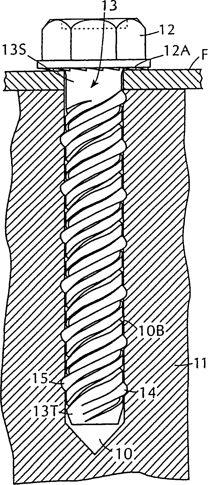
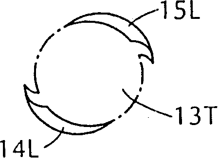
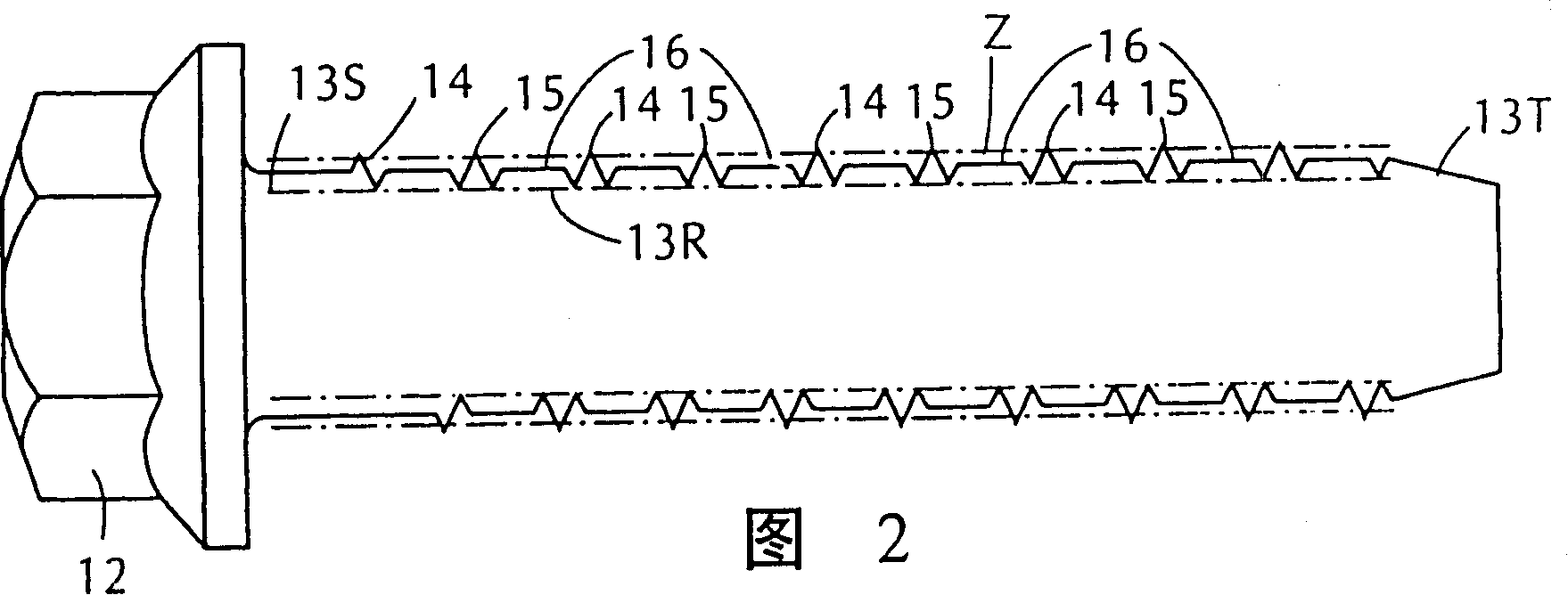
[0032] see now figure 1 , 1A and 2, shown in these drawings is a screw self-tapping masonry anchor according to the present invention, which is installed in a hole 10 drilled in a masonry body 11 to attach a fitting F or other accessories are fastened on it. The anchor is inserted into the masonry hole through a mounting hole on the fitting aligned with the masonry hole. The masonry consists of concrete or other stone masonry materials.

[0033] An anchor made of heat-treated hardened steel or other high-strength, corrosion-resistant metal has a large hexagonal head 12 to enable it to cooperate with a wrench or other torque-generating tool to drive the anchor into the hole middle. When the anchor is tightened, the underside 12A of the head 12 is serrated to frictionally fit the surface of the fitting.

[0034] The masonry anchors disclosed herein are screws with a large head. However, in practice the anchor may be of the screw type, wherein the upper end of the anchor is...


PUM


Abstract

An enhanced strength screw-type, self-tapping masonry anchor for fastening a fixture or other attachment to masonry in which a hole is drilled to receive the anchor. The anchor is provided with a shank having a root section surrounded by at least one helical male cutting thread whose crest diameter exceeds the diameter of the hole whereby when the anchor is screwed into the hole, the cutting thread then cuts a female thread in the bank of the hole to mechanically retain the anchor therein to impart to the anchor a holding power that resists axial pull-out forces. Formed on the root in the helical land between successive convolutions of the thread is a ridge that is raised above the root to define a compacting zone between the ridge and the bank of the hole. Particulate debris produced by the cutting action is discharged into the land and forced into the compacting zone to create a dense mass that wedges the anchor in the hole and thereby enhances the holding power of the anchor.

Description

technical field [0001] The present invention relates generally to a masonry anchor for fastening an accessory to a masonry screw, the anchor being screwed into a hole drilled in the masonry to mechanically retain the anchor in Among them, it relates more particularly to an anchor of this type, which has a plurality of leading cutting threads which improve the holding force of the anchor. Background technique [0002] For fastening fittings and other accessories to masonry, a screw anchor is used for this purpose, such as those disclosed in US Patent Nos. 5,118,496 and 5,282,708 to Giannuzzi. In such an anchor, a helical cutting thread is formed on the neck portion thereof, and when the anchor is screwed into a hole drilled in masonry, the cutting thread acts on the opening of the hole. The wall is cut and threaded to mechanically retain the anchor therein. The anchor's resistance to axial pullout force indicates its holding power. [0003] The term "masonry" is a general ...

Claims


Application Information

Patent Timeline
IPC IPC(8): F16B25/00F16B35/04
CPCF16B35/041F16B25/00F16B25/0026F16B25/0047F16B25/0068
Inventor 安东尼·C·简努兹露易斯·N·简努兹
Owner 安东尼·C·简努兹
Learn More