
High-rigidity beam structure

A beam structure, high rigidity technology, applied in the direction of structural elements, elongated structural members for load-bearing, truss-type structures, etc., can solve problems such as insufficient beam rigidity, reduce static deformation of the structure, simple structure, and convenient transportation. Effect

Inactive Publication Date: 2020-02-11
SOUTHEAST UNIV
View PDF5 Cites 0 Cited by
  • Summary
  • Abstract
  • Description
  • Claims
  • Application Information

AI Technical Summary

Problems solved by technology

[0006] Purpose of the invention: the purpose of the invention is to provide a high-rigidity beam structure to solve the problem of insufficient rigidity of existing beams

Method used


Image

  • High-rigidity beam structure
  • High-rigidity beam structure
  • High-rigidity beam structure

Examples


Embodiment Construction

[0020] The present invention will be further described below in conjunction with accompanying drawing and embodiment:

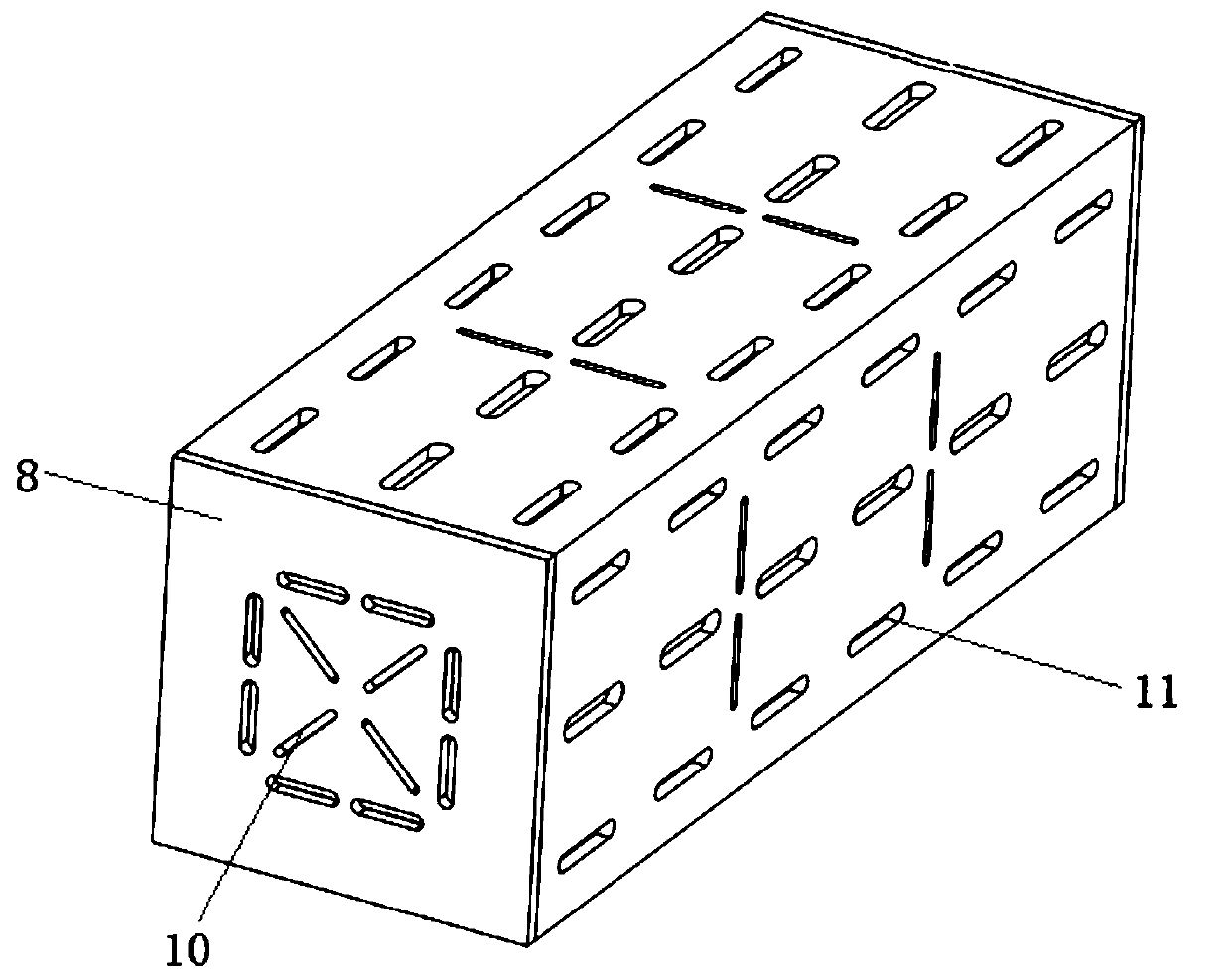
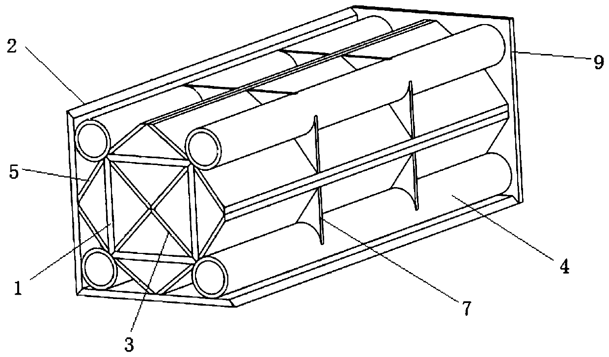
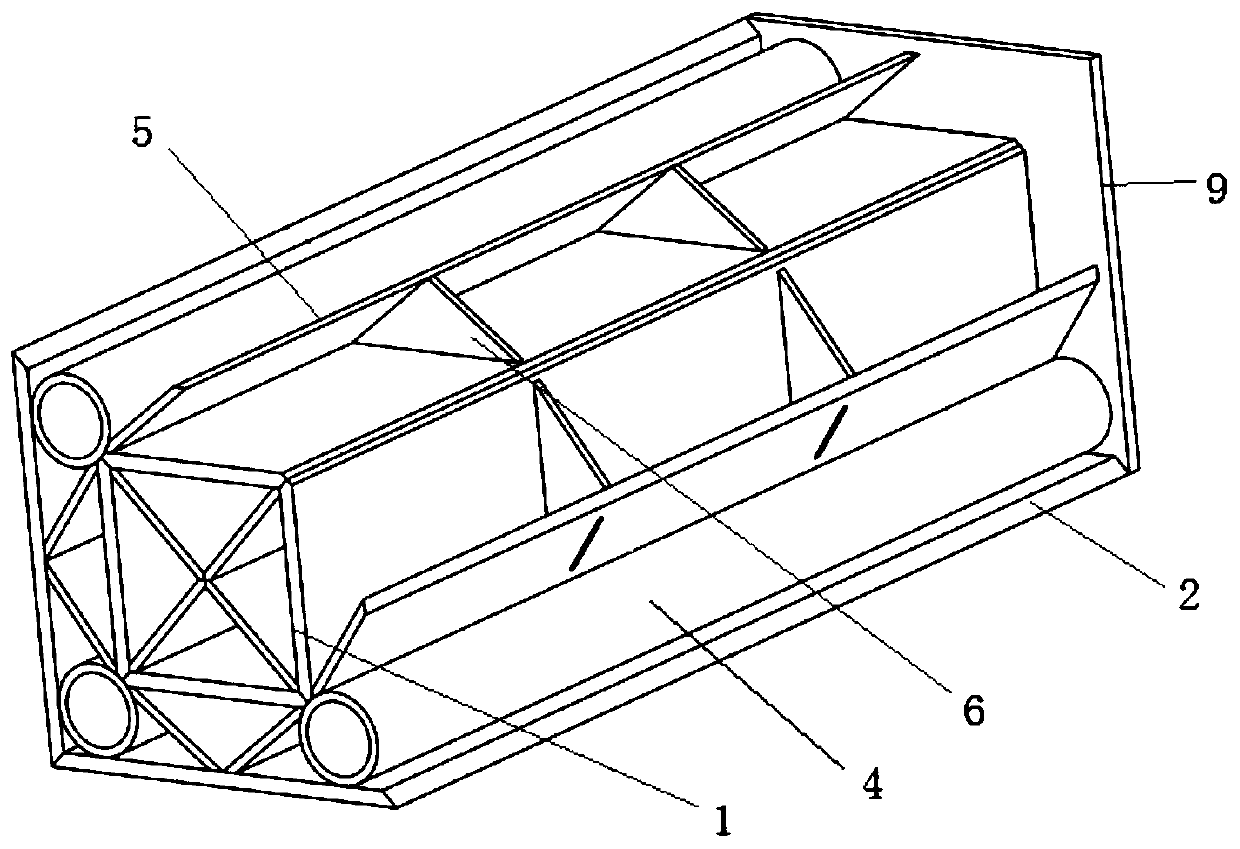
[0021] Such as Figure 1 to Figure 3 As shown, a high-rigidity beam structure of the present invention comprises a central beam 1 formed by four groups of flat plates connected end to end by sequential welding to form a square cross section and an outer frame 2 formed by four groups of side plates connected by end to end sequentially welded to form a square cross section. The beam 1 is located inside the outer frame 2 and the center beam 1 and the outer frame 2 form a back-shaped structure. The side edges of the center beam 1 are respectively welded with a center plate 3 extending toward the center line of the center beam 1. There are four sets of center plates 3. The center plate 3 intersects at the centerline of the center beam 1 and is fixed by welding. An angle tube 4 is welded between the side edge of the center beam 1 and the inner side wall of the oute...


PUM


Abstract

The invention discloses a high-rigidity beam structure. The high-rigidity beam structure comprises a center bema and an outer frame, wherein the center beam is formed by sequentially connecting four flat plates end to end, and the section of the center beam is square; and the outer frame is formed by sequentially connecting four edge plates end to end, and the section of the outer frame is square.The center beam is located in the outer frame, and a hollow-square structure is formed by the center beam and the outer frame. Center plates which extend towards the center line of the center beam are welded to the side edges of the center beam, intersect with the center line of the center beam and are fixed through welding. Angular pipes are welded between the side edges of the center beam and the inner side walls of the outer frame. Circle centers of the angular pipes are located on the diagonal lines of the outer frame, and the angular pipes are tangent to the two inner side walls of the outer frame. Oblique support plates which extend towards the center lines of the edge plates of the outer frame are welded to the adjacent edges of the center beam. By the adoption of the high-rigiditybeam structure, the rigidity of a beam can be improved; and the beam structure is high in bending resistance and twisting resistance and simple and symmetrical in structure, and the size of the structure can be flexibly designed according to the actual condition.

Description

technical field [0001] The invention relates to the technical field of beam structures bearing relatively large loads, in particular to a beam structure with high rigidity. Background technique [0002] There are many occasions in the modern industrial field that require the use of beams that bear large loads. Due to the requirements for equipment accuracy, reliability, stability, etc., the deformation of the beam subjected to large bending moment and large torque must be strictly controlled. This requires the beam to have high rigidity. [0003] The existing common beam structures that bear large loads have insufficient rigidity, resulting in large deformation of the structure, seriously reducing the accuracy and stability of the equipment, and even making the equipment unable to work normally. For example, the beam of the gantry machine tool is subjected to large bending moment and large torque during work, and insufficient rigidity will lead to a decrease in the machini...

Claims


Application Information

Patent Timeline
Patent Type & Authority Applications(China)
IPC IPC(8): E04C3/04E04C3/08
CPCE04C3/04E04C3/083E04C2003/0413E04C2003/0426E04C2003/043E04C2003/0465
Inventor 卢熹李昌陆云桥
Owner SOUTHEAST UNIV
Learn More