
High-precision stand column pile positioning and perpendicularity-regulating device

A column pile, high-precision technology, applied in the direction of sheet pile wall, building, foundation structure engineering, etc., can solve the problems of large positioning deviation, low verticality precision control, etc., achieve long solution time, reduce the difficulty of vertical adjustment, and control accuracy high effect

Pending Publication Date: 2020-02-11
中煤江南建设发展集团有限公司
View PDF0 Cites 2 Cited by
  • Summary
  • Abstract
  • Description
  • Claims
  • Application Information

AI Technical Summary

Problems solved by technology

[0003] In order to solve the above-mentioned problems of low verticality accuracy control and large positioning deviation of the traditional column pile steel structure column installation, the present invention provides a high-precision column pile positioning and vertical adjustment device, which uses a vertical adjustment correction frame combined with a real-time dynamic verticality monitoring instrument , can greatly improve the installation and positioning accuracy of the steel structure column, and effectively prevent the influence of the column pile concrete pouring process on the extrusion deviation of the steel structure column, avoiding the cost of subsequent reinforcement and the loss of construction period

Method used


Image

  • High-precision stand column pile positioning and perpendicularity-regulating device
  • High-precision stand column pile positioning and perpendicularity-regulating device
  • High-precision stand column pile positioning and perpendicularity-regulating device

Examples


Embodiment Construction

[0014] The present invention will be further described in detail below through specific embodiments in conjunction with the accompanying drawings. The present application can be implemented in many different forms, and is not limited to the implementation manner described in this embodiment. The purpose of providing the following specific embodiments is to facilitate a clearer and more thorough understanding of the disclosure of the present application, wherein the words indicating orientation such as front, rear, up, and down are only for the positions of the structures shown in the corresponding drawings.

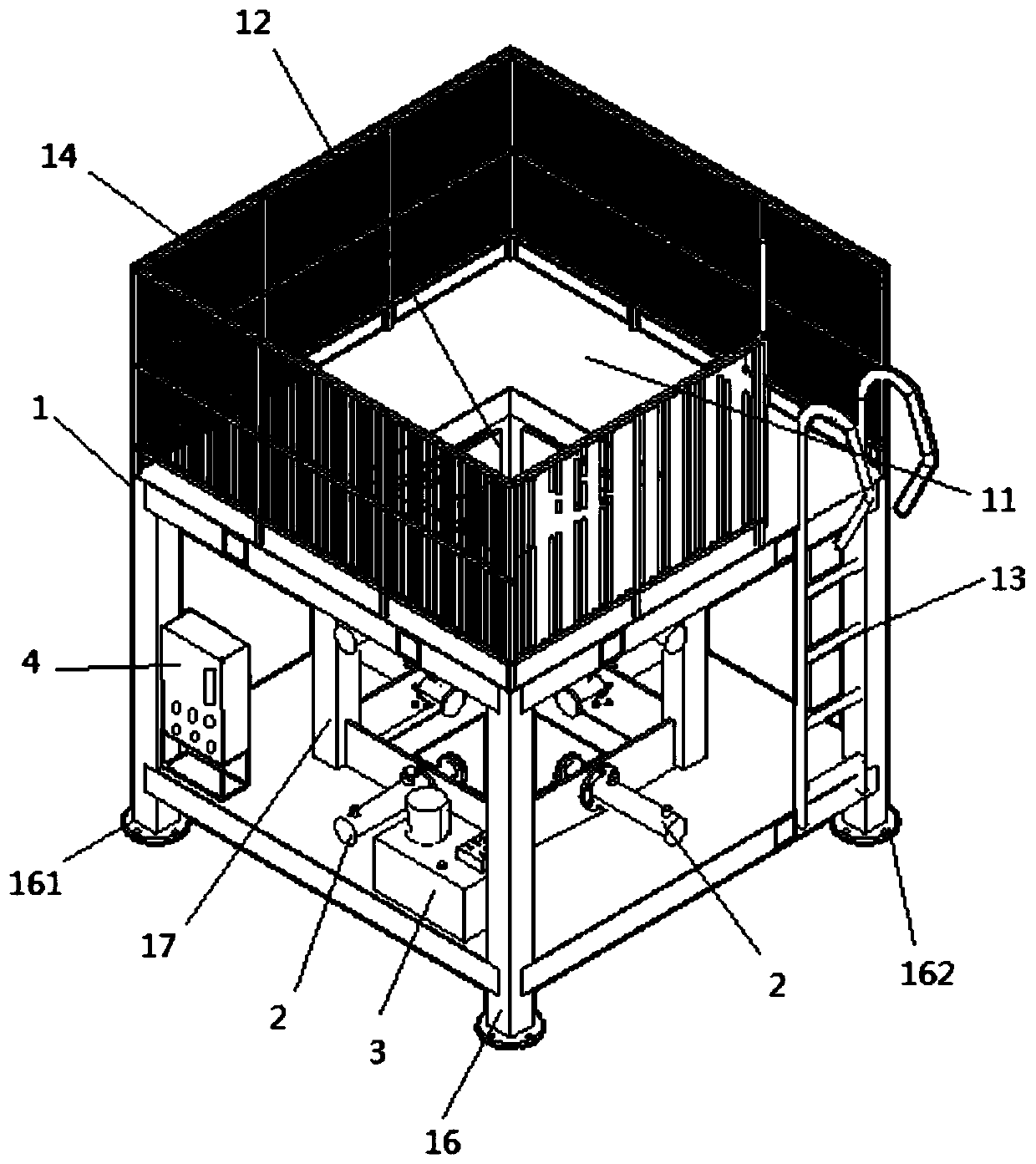
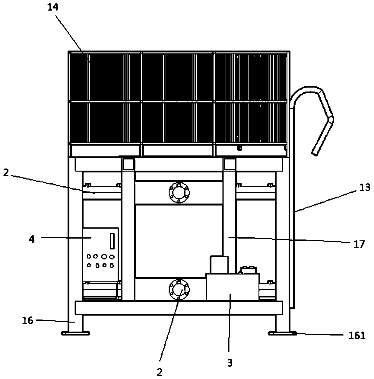
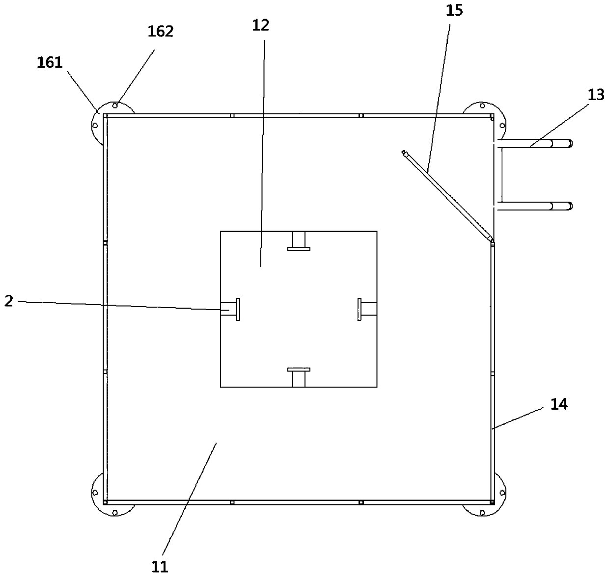
[0015] see Figure 1-3 As shown, the present invention relates to a high-precision column pile positioning and vertical adjustment device, including a correction frame 1, a jacking device 2, a hydraulic oil pump 3 and a control box 4, and the upper end of the correction frame 1 is provided with a working platform 11, so that The center of the correction frame 1 is provid...


PUM


Abstract

The invention relates to the field of positioning and perpendicularity-regulating devices, in particular to a high-precision stand column pile positioning and perpendicularity-regulating device. The high-precision stand column pile positioning and perpendicularity-regulating device comprises a correcting rack, jacking devices, a hydraulic oil pump and a control box, wherein the upper end of the correcting rack is equipped with an operating platform; one side of the correcting rack is further equipped with a ladder stand; a steel structure column mounting hole which is through from top to bottom is formed in the center of the correcting rack; the jacking devices are horizontally mounted inside the correcting rack; the jacking devices are separately mounted on front, rear, left and right positions of the steel structure column mounting hole in a surrounding mode; and the hydraulic oil pump and the control box are separately fixed at one side inside the correcting rack. The high-precisionstand column pile positioning and perpendicularity-regulating device is high in mechanical degree, is simple and convenient in operation, reduces perpendicularity-regulating difficulty, can effectively prevent steel structure column deviation caused by guide tube displacement and lifting, and concrete extrusion in pile holes in a concrete filling process, is high in control precision, and furthersolves the technical problems of long manual perpendicularity-regulating and deviation-correcting time and easy steel structure column deviation.

Description

technical field [0001] The invention relates to the field of positioning and vertical adjustment devices, in particular to a high-precision column pile positioning and vertical adjustment device, which is suitable for the positioning of steel pipe columns and angle steel columns of column piles and the construction of verticality deviation correction. Background technique [0002] The traditional column pile vertical adjustment usually uses a combination of total station and pendant hammer to control the positioning and verticality of the steel column installation, that is, after the steel column and the steel cage are welded firmly, the positioning control is measured and placed around the opening of the hole. Point and pull the "well" line positioning control line, and then slowly lower the steel structure column, and at the same time use the hanging hammer to observe the verticality. In this method, the installation control accuracy of the steel structure column is low, a...

Claims


Application Information

Patent Timeline
Patent Type & Authority Applications(China)
IPC IPC(8): E02D13/04
CPCE02D13/04
Inventor 刘建雄暨雷庭刘鹏张四善王双双薛琦
Owner 中煤江南建设发展集团有限公司
Learn More