
Large-span steel truss combined continuous beam structure and construction method thereof

A technology of large-span and beam structure, applied in bridges, bridge parts, bridge construction, etc., can solve the problems of inconvenient steel structure maintenance, high construction precision requirements, and large overall height, so as to avoid excessive creep deflection and facilitate maintenance , the effect of transparent shape

Pending Publication Date: 2020-02-11
CREEC WUHAN SURVEY DESIGN & RES
View PDF0 Cites 8 Cited by
  • Summary
  • Abstract
  • Description
  • Claims
  • Application Information

AI Technical Summary

Problems solved by technology

[0006] The purpose of the present invention is to overcome the existing long-span bridges with concrete beams as the main force-bearing structure and steel structures as the stiffening structure, which require high construction accuracy, large overall height, and are restricted by the height limit of aviation. The problem of facilitating steel structure maintenance

Method used


Image

  • Large-span steel truss combined continuous beam structure and construction method thereof
  • Large-span steel truss combined continuous beam structure and construction method thereof
  • Large-span steel truss combined continuous beam structure and construction method thereof

Examples


Embodiment Construction

[0031] The following will clearly and completely describe the technical solutions in the embodiments of the present invention with reference to the accompanying drawings in the embodiments of the present invention. Obviously, the described embodiments are only some, not all, embodiments of the present invention. Based on the embodiments of the present invention, all other embodiments obtained by persons of ordinary skill in the art without making creative efforts belong to the protection scope of the present invention.

[0032] In describing the present invention, it is to be understood that the terms "center", "upper", "lower", "front", "rear", "left", "right", "vertical", "horizontal", The orientations or positional relationships indicated by "top", "bottom", "inner", "outer", etc. are based on the orientations or positional relationships shown in the drawings, and are only for the convenience of describing the present invention and simplifying the description, rather than in...


PUM


Abstract

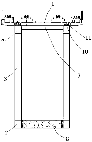
The invention provides a large-span steel truss combined continuous beam structure. The beam structure comprises a concrete deck slab, two steel trusses, a side span fulcrum and a middle fulcrum; thesteel trusses comprise upper chord members and lower chord members, wherein a plurality of web members are connected between the upper chord members and the lower chord members; the upper chord members are of horizontal straight rod structures, an upper parallel-connection structure is arranged between the two upper chord members, and the concrete deck slab is connected with the upper chord members of the steel trusses; and the lower chord members are in parabolic shapes, a concrete bottom plate is arranged between the two lower chord members in a side span overall length area and a middle span negative bending moment area, and a lower parallel-connection structure is arranged between the two lower chord members in a middle span remaining area. According to the beam structure, a steel truss beam is adopted as main stressed structure, the concrete deck slab is combined with the upper chord members, the concrete bottom plate is arranged in the side span and main span partial areas and combined with the lower chord members, so that the light weight and high strength characteristics of a steel structure are fully exerted, the beam structure can adapt to larger bridge spans, the residual creep down deflection value of the combined beam is extremely small, and the structure total height of the combined beam is smaller than that of other concrete combined structure bridges.

Description

technical field [0001] The invention belongs to the technical field of bridge design and construction, and in particular relates to a long-span steel truss composite continuous beam structure and a construction method thereof. Background technique [0002] High-speed railways have very strict requirements on the deformation and settlement of bridges and roadbeds, which is one of the key controlling factors in the selection of high-speed railway bridges. Prestressed concrete beams have the advantages of high rigidity, good dynamic performance, and easy maintenance and repair, and are the preferred beam type for railway bridges. However, the concrete structure has the characteristics of shrinkage and creep, and the mid-span deflection will gradually increase with time. At present, the maximum span of prestressed concrete continuous beams for high-speed railways is about 135m. In theory, when it exceeds 150m, it is difficult to control the residual creep deflection after track...

Claims


Application Information

Patent Timeline
Patent Type & Authority Applications(China)
IPC IPC(8): E01D19/00E01D21/00
CPCE01D19/00E01D21/00
Inventor 李前名邹向农王旋龙俊贤牛军辉马行川范昕
Owner CREEC WUHAN SURVEY DESIGN & RES
Learn More