
Device and method for reducing standby power consumption of direct-current charging pile

A technology of DC charging piles and standby power consumption, which is applied in the direction of coin-operated equipment for distributing discrete items, coin-operated equipment for renting items, charging stations, etc., which can solve problems such as waste of power resources and reduce the number of actions , reduced standby power consumption, and the effect of energy-saving operation times

Pending Publication Date: 2020-02-11
山西千丰电器设备有限公司
View PDF10 Cites 3 Cited by
  • Summary
  • Abstract
  • Description
  • Claims
  • Application Information

AI Technical Summary

Problems solved by technology

[0004] The present invention provides a device and method for reducing the standby power consumption of a DC charging pile, aiming to solve the problem that the power consumption of a single module reaches an astonishing 500W without charging, and the standby power consumption of a 60KW charging pile exceeds 2KW , if the daily standby time is calculated as 5 hours, the annual standby power waste will reach 2*5*365=3650 kilowatt-hours, which will cause a lot of waste of power resources

Method used


Image

  • Device and method for reducing standby power consumption of direct-current charging pile
  • Device and method for reducing standby power consumption of direct-current charging pile
  • Device and method for reducing standby power consumption of direct-current charging pile

Examples


Embodiment Construction

[0033] In order to make the object, technical solution and advantages of the present invention clearer, the present invention will be further described in detail below in conjunction with the accompanying drawings and embodiments. It should be understood that the specific embodiments described here are only used to explain the present invention, not to limit the present invention.

[0034] In describing the present invention, it should be understood that the terms "length", "width", "upper", "lower", "front", "rear", "left", "right", "vertical", The orientation or positional relationship indicated by "horizontal", "top", "bottom", "inner", "outer", etc. are based on the orientation or positional relationship shown in the drawings, and are only for the convenience of describing the present invention and simplifying the description, rather than Nothing indicating or implying that a referenced device or element must have a particular orientation, be constructed, and operate in a ...


PUM


Abstract

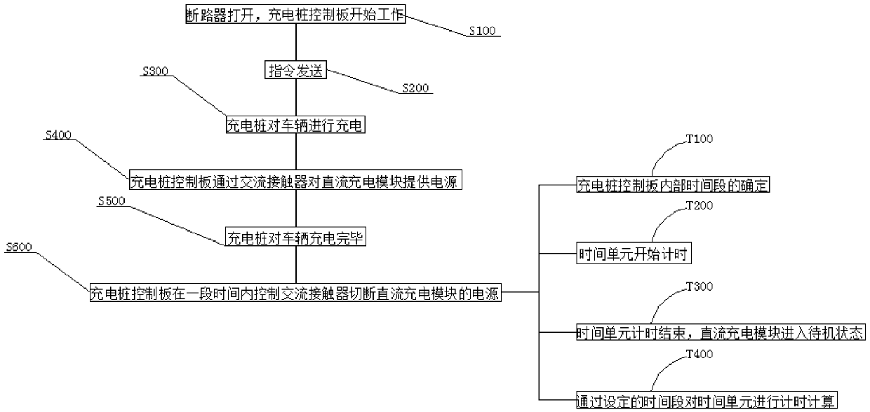
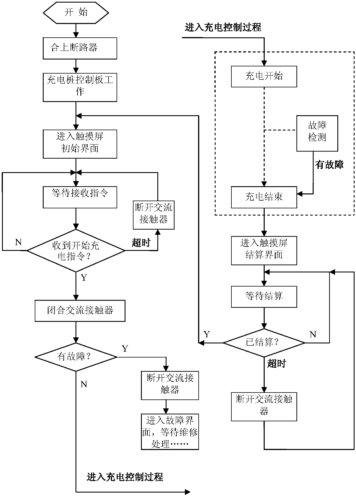
The invention discloses a device and method for reducing standby power consumption of a direct-current charging pile. The method comprises the following steps: a circuit breaker is opened, a chargingpile control panel starts to work, and the charging pile control panel starts to work when a vehicle needs to be charged; an instruction is sent, and an operator sends the instruction to the chargingpile control panel through a touch screen; the charging pile control panel provides a power supply for a direct-current charging module through an alternating-current contactor, and the alternating-current contactor controls power supply of the direct-current charging module; the charging pile control panel controls one alternating-current contactor to provide the power supply for the direct-current charging module, after one charging process is completed, the charging pile control panel controls the alternating-current contactor to disconnect the power supply of the direct-current charging module after delaying for a period of time through a time unit, energy conservation is considered, and the action frequency of the alternating-current contactor is reduced. After the method is implemented, the standby power consumption is reduced to 20W or below and is not obviously increased along with the capacity of the charging pile.

Description

technical field [0001] The invention belongs to the technical field of charging piles, and in particular relates to a device and a method for reducing the standby power consumption of a DC charging pile. Background technique [0002] With the rapid development of the charging pile market, the number of DC charging piles has increased significantly. According to incomplete statistics, as of October 2017, the total number of charging piles in my country has exceeded 190,000, including 76,000 AC charging piles and 5.1 DC charging piles. 10,000 units, and 66,000 units of AC and DC integrated charging piles. With such a large number of DC charging piles, the total standby power consumption is astonishing. The average standby power consumption of charging piles on the market is about 150W. At present, the method of reducing standby power consumption of charging piles is mainly to use modules with low standby power consumption. At present, due to the limitation of the internal tech...

Claims


Application Information

Patent Timeline
Patent Type & Authority Applications(China)
IPC IPC(8): B60L53/31G07F15/00B60L53/302
CPCG07F15/005Y02T10/70Y02T10/7072Y02T90/12
Inventor 李永格
Owner 山西千丰电器设备有限公司
Learn More