A debugging system and method capable of being integrated into a detection system

A technology of debugging system and debugging method, which is applied in the direction of radio wave measurement system, measuring device, electric/magnetic exploration, etc., can solve the problem of lack of debugging result display ability of debugging equipment, inconvenient quick debugging of magnetic detection system, and complicated debugging system software To achieve the effect of improving human-computer interaction capabilities, eliminating the need for debugging equipment design and manufacturing, and reducing labor costs

Active Publication Date: 2021-07-13
NAVAL UNIV OF ENG PLA
View PDF0 Cites 0 Cited by
  • Summary
  • Abstract
  • Description
  • Claims
  • Application Information

AI Technical Summary

Problems solved by technology

[0006] (1) At present, the function debugging of the magnetic module in the magnetic detection system is carried out through the external interface of the system with special debugging equipment and according to certain debugging steps, which often requires a lot of manpower and material resources
[0007] (2) The debugging steps are cumbersome and single, inflexible, and the error of one step is completely wrong
[0008] (3) The debugging quality is not high, only the internal software can be debugged, and the hardware integrity of the detection system is lacking.
[0009] (4) The debugging system software is complicated, and the whole set of debugging takes a long time to complete, which is not convenient for the quick debugging of the magnetic detection system
[0010] (5) The debugging results are not easy to distinguish. The existing debugging equipment lacks the ability to display the debugging results. There are only a few indicators to output the results. The debugging results need to be judged manually, which is prone to errors
[0012] (1) How to design a debugging system that can be integrated into the detection system needs to solve the compatibility problem between the detection system and the debugging system

Method used


Image

  • A debugging system and method capable of being integrated into a detection system
  • A debugging system and method capable of being integrated into a detection system
  • A debugging system and method capable of being integrated into a detection system

Examples


Embodiment Construction

[0094] In order to make the object, technical solution and advantages of the present invention clearer, the present invention will be further described in detail below in conjunction with the examples. It should be understood that the specific embodiments described here are only used to explain the present invention, not to limit the present invention.

[0095] At present, the function debugging of the magnetic module in the magnetic detection system is carried out through the external interface of the system with special debugging equipment and according to certain debugging steps, which often requires a lot of manpower and material resources.

[0096] Aiming at the problems existing in the prior art, the present invention provides a debugging system and method that can be integrated into the detection system. The present invention will be described in detail below in conjunction with the accompanying drawings.

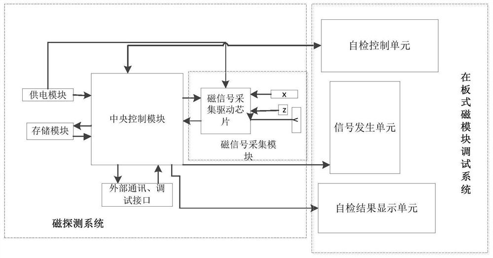
[0097] Such as figure 1 As shown, the debugging system provid...


PUM


Abstract

The invention belongs to the technical field of data information processing, and discloses a debugging system and method that can be integrated into a detection system. The magnetic detection system generates a magnetic debugging control signal, and transmits the generated magnetic debugging control signal to a plate-type magnetic module debugging system; The signal generation module of the plate-type magnetic module debugging system generates corresponding debugging signals according to the received control signals. The magnetic detection system receives and judges the collected signals, and further judges whether the function of the magnetic module is complete according to the judgment results, and finally transmits the results display system. The present invention subverts the tradition and proposes a new magnetic module debugging mode. The plate type magnetic module debugging system is completely different from the existing debugging mode. This debugging mode is directly integrated into the magnetic detection system, making full use of the existing hardware resources to complete Debugging subverts the original concept of debugging and forms a feasible debugging mode for magnetic modules, which has great theoretical guiding significance.

Description

technical field [0001] The invention belongs to the technical field of data information processing, and in particular relates to a debugging system and method which can be integrated into a detection system. Background technique [0002] Currently, the closest prior art: [0003] The Target Detecting System (TDS) perceives various characteristics of the detected target through various sensors, and then realizes the detection, identification, positioning and tracking of the target according to a certain detection technology. It is widely used in traffic monitoring and geological exploration. and military equipment. Among the various existing target detection systems, the magnetic detection system has been widely developed and applied due to its specificity that it is not restricted by the external environment. For detection and positioning; in coastal defense systems, magnetic detection systems are used to detect various intruding military targets; in high-speed traffic mon...

Claims


Application Information

Patent Timeline
Patent Type & Authority Patents(China)
IPC IPC(8): G01V3/08G01V13/00
CPCG01V3/081G01V13/00
Inventor 周穗华戴忠华单珊
Owner NAVAL UNIV OF ENG PLA
Why Eureka
Try Eureka