
Navigation interference signal transmitting method and system for synchronous angle flickering

A technology that interferes with signals and angles, applied in the field of satellite navigation testing, can solve problems such as the absence of synchronous angle flicker interference, and the inability to achieve millisecond-level flicker cycle time synchronization, etc., to achieve maximum flexibility and facilitate the traversal of launch parameters

Active Publication Date: 2020-02-07
HUNAN SATELLITE NAVIGATION INFORMATION TECH CO LTD
View PDF7 Cites 2 Cited by
  • Summary
  • Abstract
  • Description
  • Claims
  • Application Information

AI Technical Summary

Problems solved by technology

However, the disadvantage of existing interference signal sources is that they only support interference pattern switching and power switching, but they cannot achieve millisecond-level flickering periods and precise time synchronization, and cannot be directly used for synchronous angle flickering experiments.
Patent CN107817478B is an asynchronous angle scintillation method applied to radar scintillation interference, and has no reference significance for synchronous angle scintillation interference in the field of satellite navigation

Method used

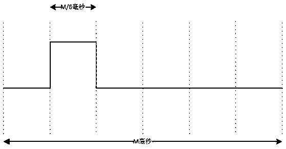

Image

  • Navigation interference signal transmitting method and system for synchronous angle flickering
  • Navigation interference signal transmitting method and system for synchronous angle flickering
  • Navigation interference signal transmitting method and system for synchronous angle flickering

Examples


Embodiment Construction

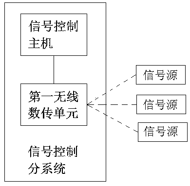
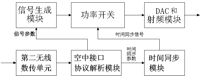
[0024] Attached below Figures 1 to 3 The preferred embodiment of the present invention is further described, including the signal control subsystem and N signal sources distributed in N positions, N≥3;

[0025] The signal control subsystem includes a signal control host connected to the first wireless data transmission unit, such as figure 1 Shown; signal parameters including interference pattern and interference power, time synchronization parameters including flicker cycle and flicker sequence number are all set on the signal control host;

[0026] The signal source is composed of a second wireless data transmission unit, an air interface protocol analysis module, a time synchronization module, a signal generation module, a power switch, a DAC and a radio frequency module, such as figure 2 As shown, the air interface protocol analysis module is connected to the second wireless data transmission unit, the signal generation module and the time synchronization module respect...


PUM


Abstract

The invention relates to a navigation interference signal transmitting method and system for synchronous angle flickering, belongs to the technical field of satellite signal source control. The systemcomprises a signal control sub system and N signal sources distributed at N positions, wherein N>=3; signal parameters and time synchronization instruction are framed according to an air interface protocol and then sent to the N signal sources through a wireless link of a first wireless data transmission module; and the N signal sources periodically send non-coherent signals to a target from eachangle to form angle flicker signal emission. The navigation interference signal transmitting method and system have the beneficial effects that accurate time synchronization and implementation of angle flicker interference of multiple signal sources cause failure of an anti-interference algorithm of an anti-interference receiver, the receiver cannot perform normal positioning, and a receiving endsignal direction finding and positioning system cannot measure the position coordinates of the signal sources.

Description

technical field [0001] The invention relates to a navigation interference signal transmission method and system for synchronous angle flickering, belonging to the technical field of satellite navigation testing. Background technique [0002] In the process of signal interference to the navigation terminal, the signal source is also easily attacked by the opponent's detection and positioning. Therefore, in order to improve the survival rate of the signal source, the angle scintillation signal transmission becomes a feasible signal transmission method. Scintillation jamming is currently the most widely used in radars. Patent CN107817478B, an asynchronous scintillation angle spoofing jamming method based on a phase modulation surface, discloses a scintillation jamming implementation method. However, in the anti-jamming test of satellite navigation terminals, multi-angle scintillation jamming has not been widely studied and applied. In fact, multiple interference signal sources...

Claims


Application Information

Patent Timeline
Patent Type & Authority Applications(China)
IPC IPC(8): G01C21/24G01C25/00G01S19/21
CPCG01C21/24G01C25/00G01S19/21
Inventor 张勇虎刘思慧戴志春姜果平
Owner HUNAN SATELLITE NAVIGATION INFORMATION TECH CO LTD
Learn More