
All-terrain crawler belt and belt pulley combination mechanism

A combined mechanism, all-terrain technology, used in tracked vehicles, motor vehicles, transportation and packaging, etc., can solve the problems of easy slippage, the inability of the tracked running mechanism to adapt to various road structures, and the difficulty of walking.

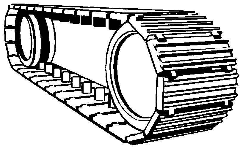
Active Publication Date: 2020-02-07
必飞科技(佛山)有限公司
View PDF7 Cites 3 Cited by
  • Summary
  • Abstract
  • Description
  • Claims
  • Application Information

AI Technical Summary

Problems solved by technology

[0007] The technical solution of the present invention is provided to solve the problem that the existing crawler walking mechanism cannot adapt to various road surface structures, especially when walking on special road surface structures, it is easy to cause damage to the road surface material or to take off the belt.
The main purpose of the present invention is to realize all-terrain walking, focusing on solving the problems of difficult walking and easy slipping on special roads, especially rough roads and climbing stairs

Method used


Image

  • All-terrain crawler belt and belt pulley combination mechanism
  • All-terrain crawler belt and belt pulley combination mechanism
  • All-terrain crawler belt and belt pulley combination mechanism

Examples


Embodiment Construction

[0052] The specific structure and working principle of the all-terrain track and pulley combined mechanism provided by the present invention will be described below in conjunction with the accompanying drawings.

[0053] see Figure 2a As shown, the all-terrain track and pulley combination mechanism provided in this embodiment mainly includes the following structures:

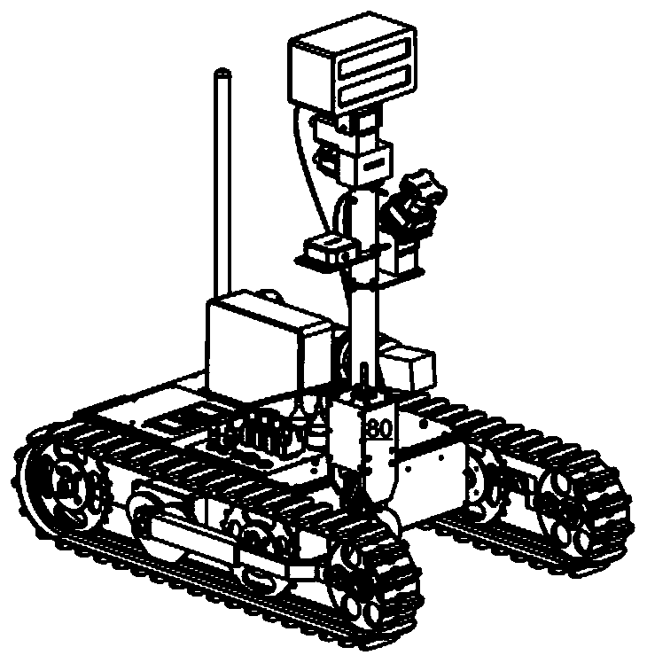
[0054] Track 1 (the material of the track can be rubber, mixed rubber or nylon, etc.), two pulleys 2 (the material of the pulley can be hard material such as metal or plastic), and the track 1 will be tightly fitted on the two pulleys 2 Above (in actual use, the number of pulleys can be selected according to actual needs). When the mechanism of the present invention is applied to a specific walking mechanism, the power of the walking mechanism will be transmitted to the track 1 through one of the pulleys 2, so that the mechanism can be used on ordinary ground, gravel roads, stairs, and mountain roads. walk. ...


PUM


Abstract

The invention provides an all-terrain crawler belt and belt pulley combination mechanism. The all-terrain crawler belt and belt pulley combination mechanism comprises belt pulleys and a crawler belt arranged on the outer sides of the belt pulleys in a sleeving mode, wherein the crawler belt comprises an outer crawler belt surface and an inner crawler belt surface, the outer crawler belt surface isprovided with crawler belt outer teeth protruding outwards at intervals, the portions, between the crawler belt outer teeth, of the outer crawler belt surface form outer crawler belt concave surfaces, the inner crawler belt surface is provided with crawler belt inner teeth protruding outwards, inwards-sunk belt pulley concave teeth are arranged at the positions, corresponding to positions of thecrawler belt inner teeth, of the contact portions between the outer sides of the belt pulleys and the crawler belt, the structures of the belt pulley concave teeth are matched with the structures of the crawler belt inner teeth, the belt pulley concave teeth are penetrating type through holes, and the sides, facing the crawler belt, of the belt pulley concave teeth and the sides, facing the interiors of the belt pulleys, of the belt pulley concave teeth have permeability. The problems that an existing crawler belt walking mechanism cannot adapt to various road surface structures and the driving force of the crawler belt is poor are solved, through the cooperation of the crawler belt inner teeth and the belt pulley concave teeth having the permeability, enough driving force is provided forthe crawler belt, and meanwhile, impurities such as sand and stones mixed in the inner crawler belt also can be discharged through the belt pulley concave teeth.

Description

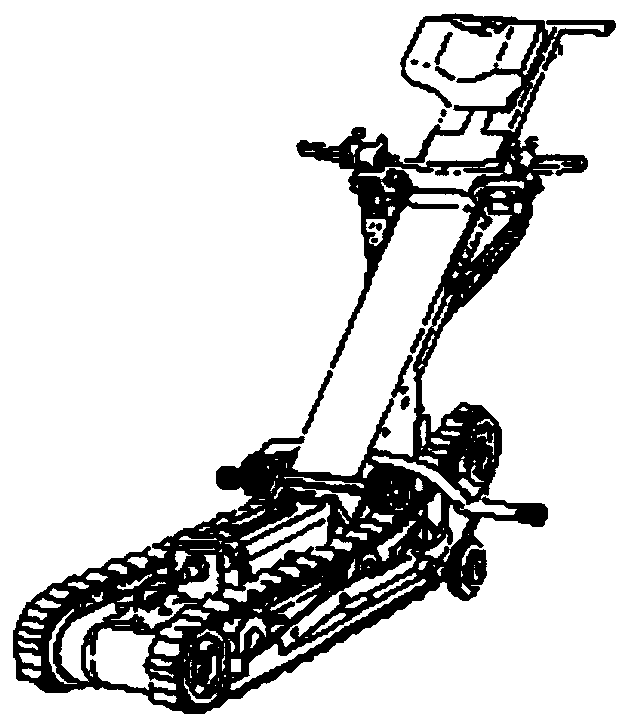
technical field [0001] The invention relates to a walking crawler structure, in particular to an all-terrain crawler and pulley combined mechanism that drives the crawler through the driving force of the crawler running mechanism to run on different grounds or stairs. Background technique [0002] The existing crawler running mechanism is mainly divided into two categories: metal crawler and rubber crawler: [0003] Metal tracks - mostly used in heavy machines such as tanks and excavators (such as Figure 1a ), the advantage is high load-bearing capacity and strong tensile strength, but due to the original solidity of the metal crawler, the walking mechanism can only walk on muddy roads and gravel roads, but the disadvantage is that if it walks on ordinary streets, it will Wreak havoc on the road. [0004] Rubber crawler - the crawler made of rubber will not cause damage to the general road surface, so the existing crawler walking mechanism, such as ( Figure 1b ) stair cl...

Claims


Application Information

Patent Timeline
IPC IPC(8): B62D55/18B62D55/26B62D55/08
CPCB62D55/08B62D55/18B62D55/26
Inventor 李少麟
Owner 必飞科技(佛山)有限公司
Learn More