An automatic fixture device suitable for CNC milling machine

A fixture device, CNC milling machine technology, applied in lighting devices, positioning devices, lighting devices and other directions, can solve the problems of reduced processing efficiency, illuminated workpieces, dangers, etc., to achieve the effect of improving processing efficiency and easy disassembly and assembly

Active Publication Date: 2021-01-01
广东德信模钢实业有限公司
View PDF6 Cites 0 Cited by
  • Summary
  • Abstract
  • Description
  • Claims
  • Application Information

AI Technical Summary

Problems solved by technology

[0003] Existing CNC milling machines cannot adjust the position of the workpiece during processing. It is necessary to open the cabinet door to manually adjust the tool setting during processing. In this case, manual operation will reduce the processing efficiency. At the same time, because there is only one large lighting fixture inside the existing milling machine, it cannot illuminate all the details of the workpiece from different angles, so it is impossible to accurately grasp the internal processing in real time. In this situation, workers need to open the cabinet door to observe, and the cutting chips at this time are easy to splash into people's eyes, which is very dangerous

Method used


Image

  • An automatic fixture device suitable for CNC milling machine
  • An automatic fixture device suitable for CNC milling machine
  • An automatic fixture device suitable for CNC milling machine

Examples


Embodiment Construction

[0021] The following will clearly and completely describe the technical solutions in the embodiments of the present invention with reference to the accompanying drawings in the embodiments of the present invention. Obviously, the described embodiments are only some, not all, embodiments of the present invention. Based on the embodiments of the present invention, all other embodiments obtained by persons of ordinary skill in the art without making creative efforts belong to the protection scope of the present invention.

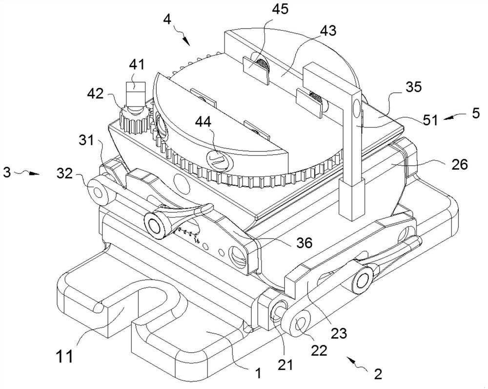
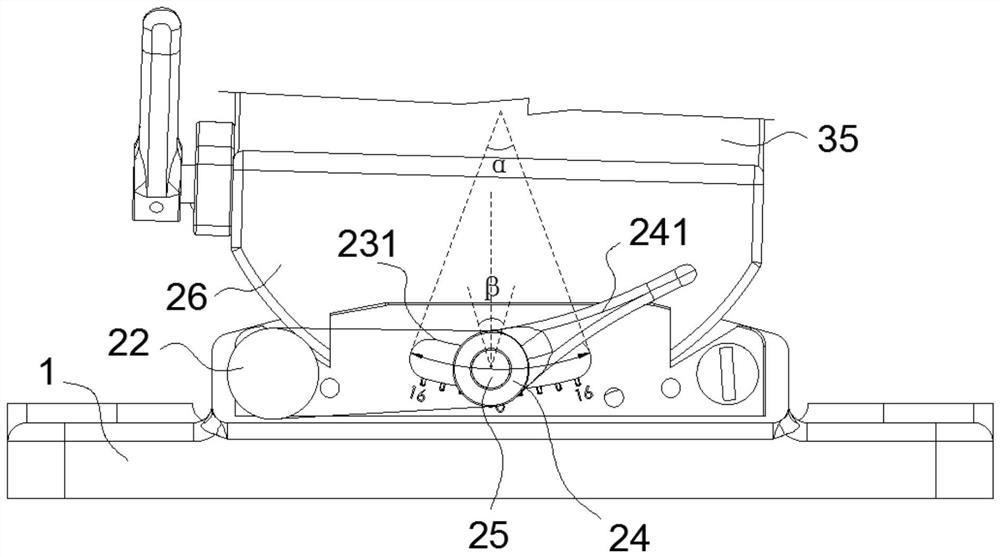
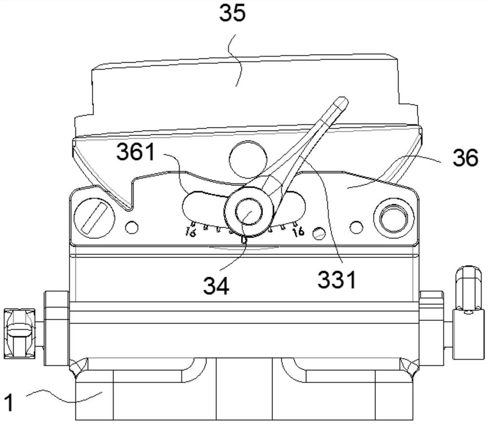
[0022] see Figure 1-5 , the present invention provides a technical solution: an automatic fixture device suitable for CNC milling machines, including a base 1, an X-direction adjustment device 2 is installed on the top of the base 1, and a Y-direction adjustment device 3 is installed on the top of the X-direction adjustment device 2, Y A clamping steering device 4 is arranged on the top of the adjusting device 3, and the base 1 combines the X-direction adjust...


PUM


Abstract

The invention discloses an automatic fixture device suitable for a numerical control milling machine, comprising a base, an X-direction adjustment device is installed on the top of the base, a Y-direction adjustment device is arranged on the top of the X-direction adjustment device, and the Y-direction adjustment device The top of the device is provided with a clamping steering device. The X-direction adjustment device includes a first bearing seat, and the two first bearing seats are correspondingly fixed on the base by bolts. One side of the first bearing seat is provided with a lower A semi-circular seat, the inside of the first bearing seat is provided with a first adjusting shaft, one side of the first bearing seat is provided with a first arc-shaped groove, and the first adjusting shaft passes through the first arc-shaped groove, One end of the first adjusting rotating shaft is sleeved with an adjusting button, the outside of the adjusting button is fixed with a first handle by welding, and the first motor is installed inside the first bearing seat. The present invention has the function of universal adjustment Good features of function and lighting effects.

Description

technical field [0001] The invention relates to the technical field of numerically controlled milling machines, in particular to an automatic fixture device suitable for numerically controlled milling machines. Background technique [0002] CNC milling machine is an automatic processing equipment developed on the basis of a general milling machine. The processing technology of the two is basically the same, and the structure is somewhat similar. CNC milling machines are divided into two categories without tool magazine and with tool magazine. Among them, the CNC milling machine with tool magazine is also called machining center. [0003] Existing CNC milling machines cannot adjust the position of the workpiece during processing. It is necessary to open the cabinet door to manually adjust the tool setting during processing. In this case, manual operation will reduce the processing efficiency. At the same time, because there is only one large lighting fixture inside the exis...

Claims


Application Information

Patent Timeline
Patent Type & Authority Patents(China)
IPC IPC(8): B23Q3/06B23Q3/04B23Q7/00F21V33/00
CPCB23Q3/04B23Q3/06B23Q7/00F21V33/00
Inventor 汪进卢志珍喻步贤朱立义
Owner 广东德信模钢实业有限公司
Why Eureka
Try Eureka