
Vaporization device

A vaporization device and shell technology, applied in chemistry, disinfection, etc., can solve the problems of high energy consumption and poor disinfection effect, and achieve the effects of low energy consumption, reduced condensed water, and good disinfection effect

Pending Publication Date: 2020-02-07
JIANGSU NEWAMSTAR PACKAGING MACHINERY
View PDF8 Cites 4 Cited by
  • Summary
  • Abstract
  • Description
  • Claims
  • Application Information

AI Technical Summary

Problems solved by technology

[0003] During the preparation of existing hydrogen peroxide vapor, some directly vaporize hydrogen peroxide solution into hydrogen peroxide vapor, which consumes relatively large energy; some atomize hydrogen peroxide first and then heat to obtain hydrogen peroxide vapor. When the hydrogen peroxide vapor flows in the pipeline, it is easy to bring out the condensed water, and the disinfection effect is relatively poor

Method used


Image

  • Vaporization device
  • Vaporization device

Examples


Embodiment Construction

[0018] The technical solution of the present invention will be further described below in conjunction with the accompanying drawings.

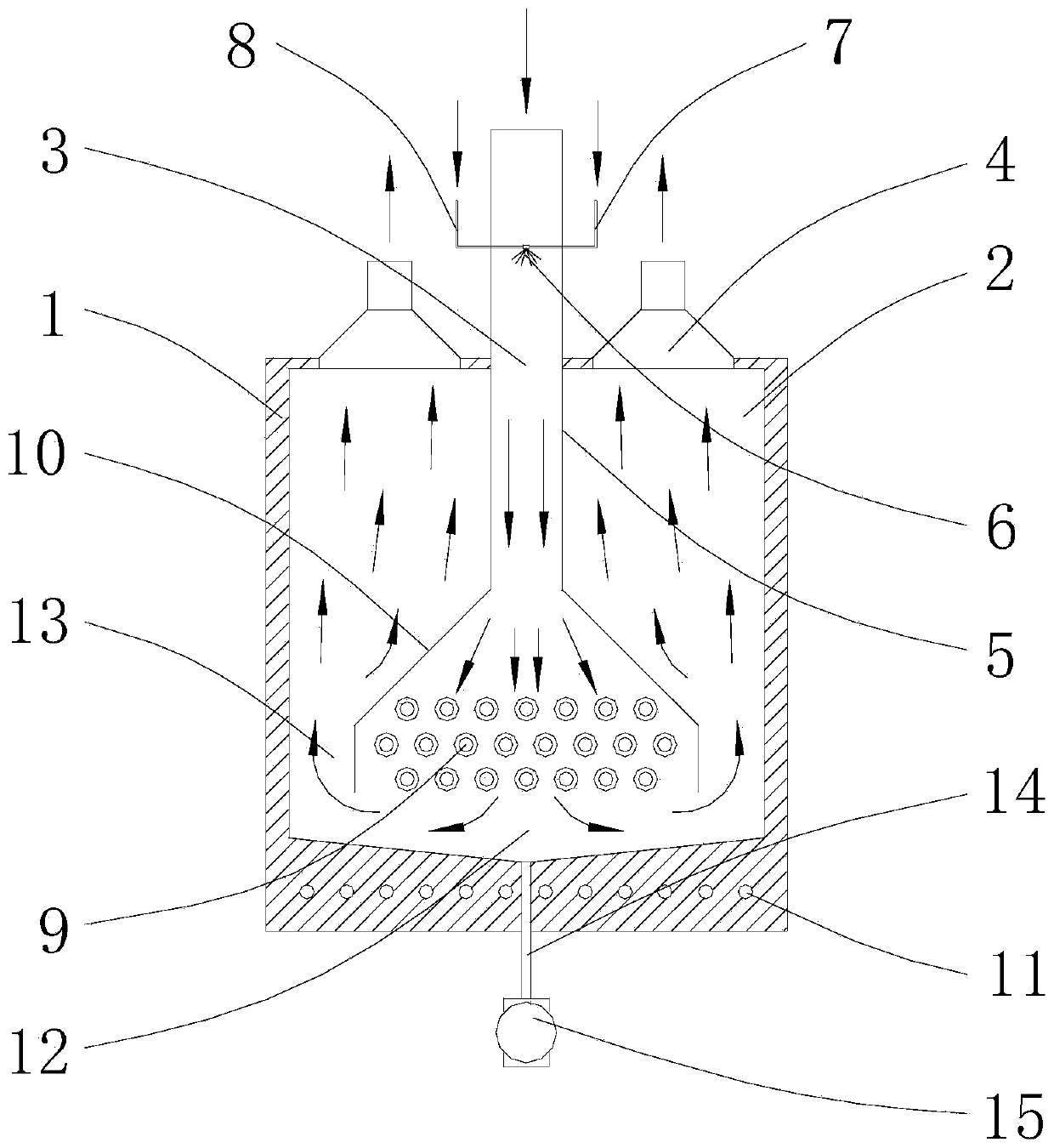
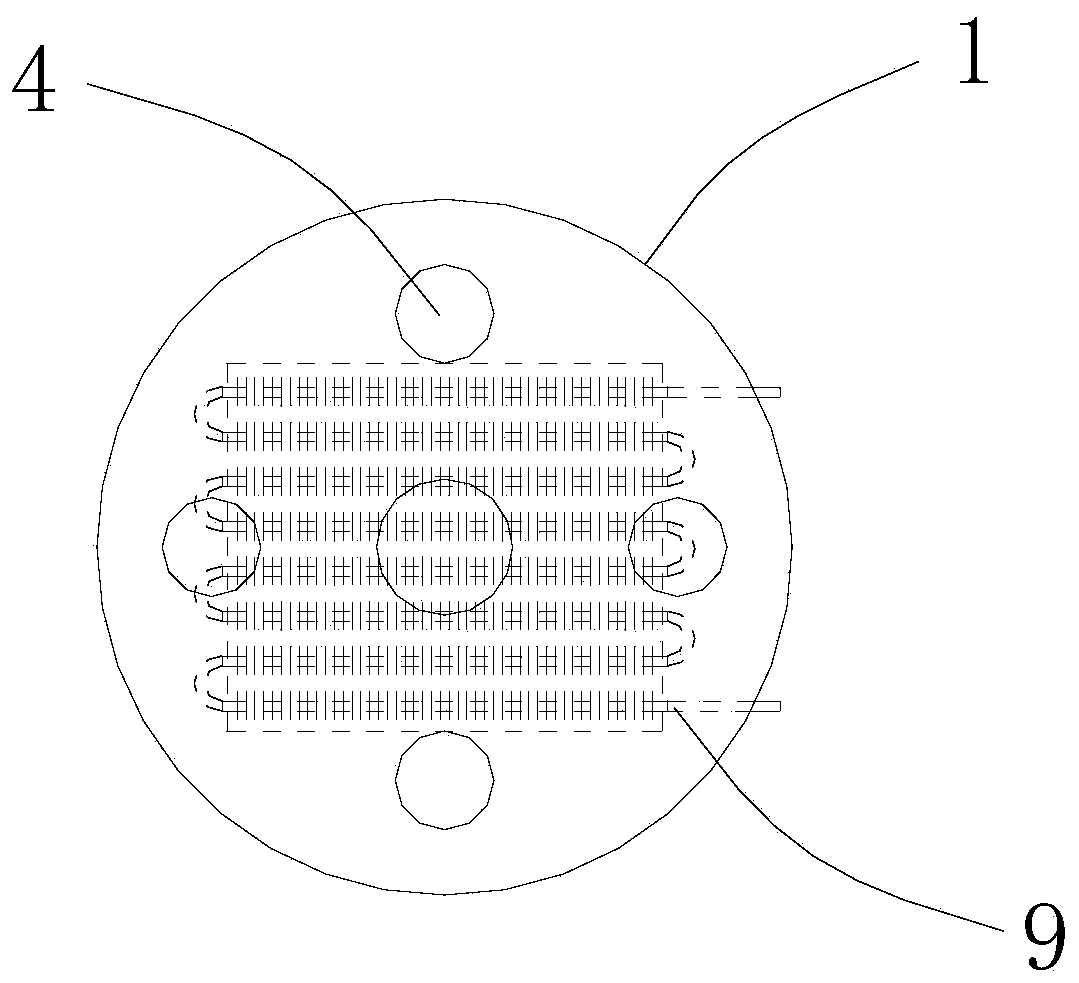
[0019] see Figure 1-2 As shown, the above-mentioned vaporization device includes a housing 1 with a hollow inner chamber 2, a feed inlet 3 and a discharge outlet 4 provided on the top of the housing 1, and a valve extending into the hollow inner chamber 2 through the feed inlet 3. The hot air duct 5, the atomizing nozzle 6 located in the hot air duct 5, the compressed air pipeline 7 and the hydrogen peroxide pipeline 8 communicated with the atomizing nozzle 6 respectively, and the hot air duct 5 located below the hollow inner cavity 2 Finned tube 9, the first heating mechanism (not shown in the figure) for passing high-temperature steam into the finned tube 9, the upper end connected to the lower end of the hot air tube 5 for covering the finned tube 9 The air cover 10 is provided with a gap between the air cover 10 and the inner surface of ...


PUM


Abstract

The invention discloses a vaporization device. The vaporization device comprises a housing with a hollow cavity, a feeding opening formed in the top of the housing, a plurality of discharging openingsformed in the top of the housing, a thermal wind pipe which extends into the hollow cavity through the feeding opening, an atomizing nozzle located in the thermal wind pipe, a compressed air pipelineand a hydrogen peroxide solution pipeline which communicate with the atomizing nozzle, a fin pipe which is located below the thermal wind pipe, in the hollow inner cavity, a first heating mechanism enabling high-temperature steam to penetrate in and out of the fin pipe, and a fan cover of which the upper end is connected to the lower end of the thermal wind pipe, and which is used for covering the fin pipe, wherein a gap allowing hydrogen peroxide solution steam to flow upwards to the discharging openings is formed between the fan cover and the inner surface of the housing. According to the vaporization device disclosed by the invention, after being atomized, hydrogen peroxide is reheated to obtain hydrogen peroxide steam, so that energy consumption is relatively low; the hydrogen peroxide steam firstly is in contact with the inner bottom surface of the housing, and then flows upwards to the discharging openings, so that the condensation water carried when the hydrogen peroxide steamflows upwards is greatly reduced, the hydrogen peroxide steam is dry, and the disinfection effect is relatively good.

Description

technical field [0001] The invention relates to the technical field of beverage production, in particular to a vaporization device. Background technique [0002] In the beverage production line, the filling environment and packaging materials need to be sterilized, and hydrogen peroxide is usually used for disinfection, and the disinfection effect of gaseous hydrogen peroxide is better than that of liquid hydrogen peroxide. [0003] During the preparation of existing hydrogen peroxide vapor, some directly vaporize hydrogen peroxide solution into hydrogen peroxide vapor, which consumes relatively large energy; some atomize hydrogen peroxide first and then heat to obtain hydrogen peroxide vapor. When the hydrogen peroxide vapor flows in the pipeline, it is easy to bring out the condensed water, and the disinfection effect is relatively poor. Contents of the invention [0004] The object of the present invention is to provide a vaporization device, the hydrogen peroxide vapo...

Claims


Application Information

Patent Timeline
IPC IPC(8): A61L2/20A61L101/22
CPCA61L2/208A61L2202/11
Inventor 刘波吴纪美周卫林杨亚军
Owner JIANGSU NEWAMSTAR PACKAGING MACHINERY
Learn More