
Grid-connection configuration method for distributed generation

A technology of distributed power supply and configuration method, which is applied in the direction of circuit devices, electrical components, AC network circuits, etc., to achieve the optimal configuration effect

Active Publication Date: 2020-02-04
QINHUANGDAO POWER SUPPLY COMPANY OF STATE GRID JIBEI ELECTRIC POWER COMPANY +1
View PDF5 Cites 0 Cited by
  • Summary
  • Abstract
  • Description
  • Claims
  • Application Information

AI Technical Summary

Problems solved by technology

Under the background of the self-operated distribution network, the present invention solves how the main body of the self-operated distribution network will coordinate new energy in the process of planning and operating the distribution network by considering the impact of demand response on the planning of the self-operated distribution network. The allocation of power generation and the mining and management of user-side resources; by considering the "planning-operation" problem of the self-operated distribution network at the same time, a two-layer opportunity constraint model for the combination of distributed power generation and demand response is established, that is, by considering The influence of various factors to achieve the optimal allocation of distributed power in the self-operated distribution network

Method used


Image

  • Grid-connection configuration method for distributed generation
  • Grid-connection configuration method for distributed generation
  • Grid-connection configuration method for distributed generation

Examples


Embodiment Construction

[0030] Below, specific embodiments of the present invention will be described in detail in conjunction with the accompanying drawings, but they are not intended to limit the present invention.

[0031] It should be understood that various modifications may be made to the embodiments disclosed herein. Accordingly, the above description should not be viewed as limiting, but only as exemplifications of embodiments. Those skilled in the art will envision other modifications within the scope and spirit of the disclosure.

[0032] The accompanying drawings, which are incorporated in and constitute a part of this specification, illustrate embodiments of the disclosure and, together with the general description of the disclosure given above and the detailed description of the embodiments given below, serve to explain the embodiments of the disclosure. principle.

[0033] These and other characteristics of the invention will become apparent from the following description of preferred...


PUM


Abstract

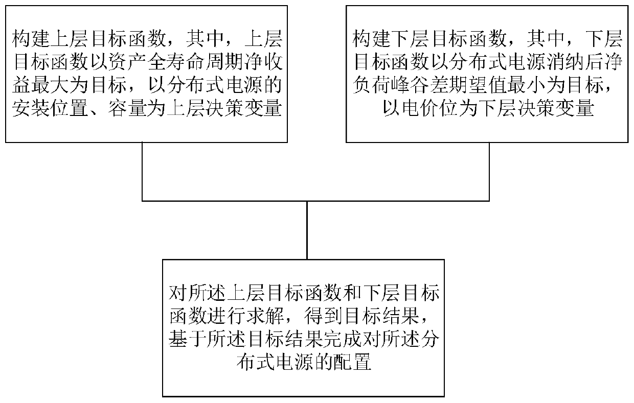
The embodiment of the invention provides a grid-connection configuration method for distributed generation. The method comprises the steps of constructing an upper-layer objective function, wherein the upper-layer objective function aims at maximizing the net income of asset in the whole life cycle and takes the installation position and the capacity of distributed generation as upper-layer decision making variables; constructing a lower-layer objective function, wherein the lower-layer objective function takes the minimum net load peak-valley difference expected value after the distributed generation is consumed as a target and takes the electricity price as a lower-layer decision making variable; and solving the upper-layer objective function and the lower-layer objective function to obtain a target result, and completing configuration of the distributed generation based on the target result. According to the invention, the problem of how to coordinate the configuration of new energypower generation and the mining and management of user side resources in the process of planning and managing the power distribution network by a self-operated power distribution network main body issolved; and a distributed generation and demand response combined double-layer opportunity constraint model is established by simultaneously considering the planning-operation problem of the self-operated power distribution network.

Description

technical field [0001] The invention belongs to the field of distribution network planning, and in particular relates to a distributed power grid-connected configuration method. Background technique [0002] In the existing technology, it is necessary to gradually release the incremental power distribution investment business to qualified market players in accordance with the requirements that are conducive to promoting the construction and development of the distribution network and improving the efficiency of power distribution operations. This means that there will be an independent distribution network operating entity, which is called self-operated distribution network here. In the process of planning and operating the distribution network, the main body of the self-operated distribution network will face the decision-making problem of how to coordinate the allocation of new energy generation and the mining and management of user-side resources to obtain greater compreh...

Claims


Application Information

Patent Timeline
Patent Type & Authority Applications(China)
IPC IPC(8): H02J3/00H02J3/38
CPCH02J3/00H02J3/008H02J3/381
Inventor 张长久赵铁军苗友忠刘长春宁文元孙荣富丁然徐海翔丁华杰聂文海李顺昕李博安磊王哲石振江苏麟钱康袁简晏阳姜华
Owner QINHUANGDAO POWER SUPPLY COMPANY OF STATE GRID JIBEI ELECTRIC POWER COMPANY
Learn More