Circularly polarized antenna
A circularly polarized antenna, circular technology, applied in antennas, resonant antennas, electrical short antennas, etc., can solve the problems of dielectric loss, reduced antenna radiation efficiency, reduced design flexibility, and complex feeding structure, etc., to achieve circular polarization Improved characteristics and scanning performance, optimized polarization characteristics, and strong radiation resistance
- Summary
- Abstract
- Description
- Claims
- Application Information
AI Technical Summary
Problems solved by technology
Method used
Image
Examples
Embodiment 1
[0019] The invention discloses a circularly polarized antenna with an all-metal structure and a fixed position. The circularly polarized characteristic of the antenna is realized by opening a C-shaped slit and a square slit on a metal radiation patch. The radiation patch is fixed by using the metal threaded connecting column and the medium connecting column, and the rotation direction of the radiation patch relative to the base is fixed by using the positioning hole on the radiation patch and the base.
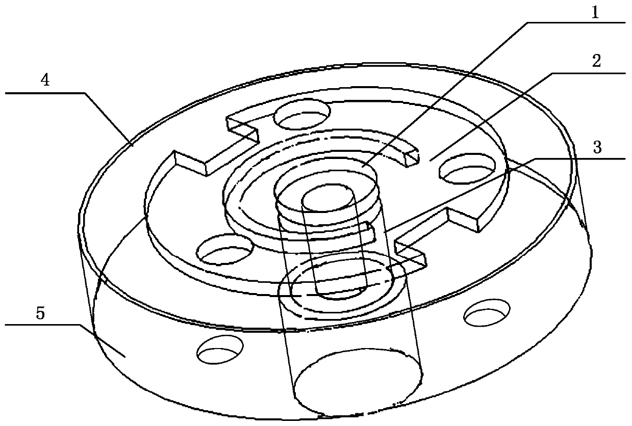
[0020] Such as figure 1 , the circularly polarized antenna includes: including: a metal connection post 1 , a radiation patch 2 , a dielectric connection post 3 , a circular metal cavity 4 and a base 5 . Among them, the circular metal cavity 4 is installed on the base 5; the metal connection column 1, the radiation patch 2 and the medium connection column 3 are located on the base 5 and inside the circular metal cavity 4; the radiation patch 2 is connected to the medium The c...
Embodiment 2
[0026] In this embodiment, the metal connection post 1 , the radiation patch 2 , the dielectric connection post 3 , the circular metal cavity 4 and the base 5 are all metal structures. Wherein, the radiation patch 2 and the medium connecting column 3 are screwed and fixed through the metal connecting column 1 , and then the medium connecting column 3 and the base 5 are screwed and fixed as a whole.
[0027] preferred, such as figure 1 , the diameter of the circular metal cavity 4 is the same as that of the base 5, the setting height of the circular metal cavity 4 is slightly higher than the radiation patch 2, and the vertical distance between the radiation patch 2 and the base 5 is about 0.075 times wavelength, the diameter of the base 5 is about 0.52 times the wavelength, so as to obtain wide beam characteristics and low unit coupling characteristics.
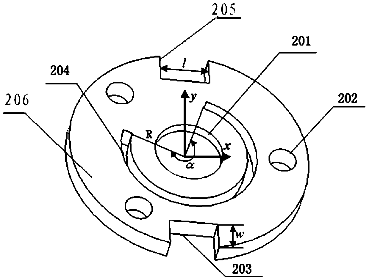
[0028] preferred, such as figure 2 , the diameter of the radiation patch 2 is about 0.4 times the wavelength, and an opti...
PUM
 Abstract
Description
Claims
Application Information
 - R&D
- Intellectual Property
- Life Sciences
- Materials
- Tech Scout
- Unparalleled Data Quality
- Higher Quality Content
- 60% Fewer Hallucinations
Browse by: Latest US Patents, China's latest patents, Technical Efficacy Thesaurus, Application Domain, Technology Topic, Popular Technical Reports.
© 2025 PatSnap. All rights reserved.Legal|Privacy policy|Modern Slavery Act Transparency Statement|Sitemap|About US| Contact US: help@patsnap.com


