Internal circuit fixing structure for circuit breaker

A technology of internal circuit and fixed structure, which is applied in the direction of circuit breaker components, circuit breaker contacts, switch terminals/connections, etc., which can solve the problem of circuit breaker failure, two contacts cannot be contacted, and moving track deviation And other issues

Active Publication Date: 2020-02-04
MINJIANG UNIV
View PDF5 Cites 0 Cited by
  • Summary
  • Abstract
  • Description
  • Claims
  • Application Information

AI Technical Summary

Problems solved by technology

[0002] A circuit breaker refers to a switching device that can close, carry and break current under normal circuit conditions and can close, carry and break current under abnormal circuit conditions within a specified time. The circuit breaker is connected to a power line In the middle position, the circuit breaker cuts off and connects the load circuit, which can cut off the faulty circuit, and then prevent the expansion of the accident and ensure the safe operation of the circuit. The inside of the circuit breaker controls the connection of the circuit through the internal circuit mechanism. The circuit breaker in the prior art The internal circuit mechanism connects the two ends of the power line through two contacts, and controls the contact and separation of the contacts to achieve the effect of controlling the opening and closing of the circuit. The contacts are divided into moving contacts and static contacts, and the moving contacts pass through The way of rotation is in contact with the static contact. After long-term use, the contact of this kind of contact may cause the running track of the moving contact to deviate, and then the two contacts cannot be contacted, which will cause the circuit breaker to fail to work normally.

Method used


Image

  • Internal circuit fixing structure for circuit breaker
  • Internal circuit fixing structure for circuit breaker
  • Internal circuit fixing structure for circuit breaker

Examples


Embodiment Construction

[0019] In order to make the above-mentioned features and advantages of the present invention more comprehensible, the following specific embodiments are described in detail with reference to the accompanying drawings.

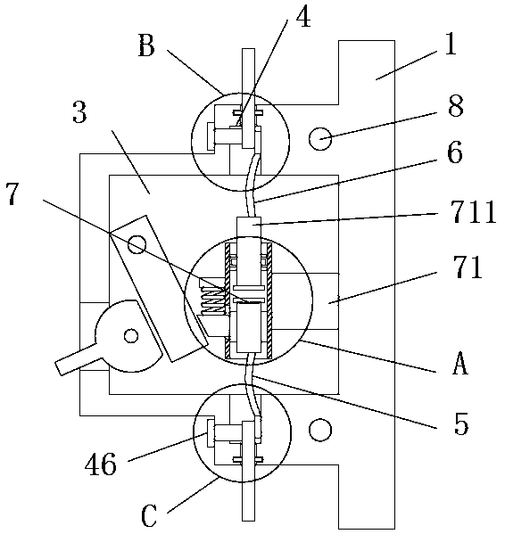
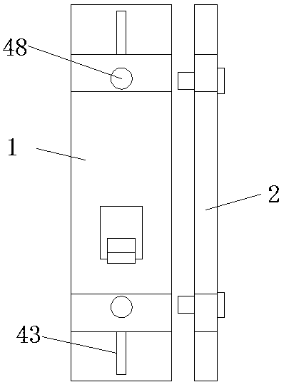
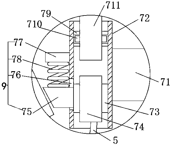
[0020] Such as Figure 1~5 As shown, a circuit breaker internal circuit fixing structure includes a housing 1, a circuit chamber 3 is opened inside the housing, two external circuit mechanisms 4 are symmetrically arranged on the upper and lower sides of the circuit chamber, and internal circuits are fixed in the circuit chamber. Mechanism 7, the internal circuit mechanism includes a fixed column 71, one end of which is fixed on the inner wall of the line cavity, and the other end is fixed on the outer wall of a vertically arranged connecting cylinder 72, the inside of the connecting cylinder is vertically hollow, and the connection A sliding sleeve 73 is slidably connected to the middle and lower sections in the barrel, and a first contact 74 is pierced inside ...


PUM


Abstract

The invention relates to an internal circuit fixing structure for a circuit breaker. The internal circuit fixing structure comprises a housing, wherein a circuit cavity is formed in the housing; two external circuit mechanisms are symmetrically arranged on the upper side and the lower side of the circuit cavity; an internal circuit mechanism is fixedly arranged in the circuit cavity and comprisesa fixed column; one end of the fixed column is fixedly connected to the inner wall of the circuit cavity, and the other end of the fixed column is fixedly connected to the outer wall of a vertically arranged connecting cylinder; the connecting cylinder is vertically hollow; the middle lower section in the connecting cylinder is connected with a sliding sleeve in a sliding manner; a first contact is arranged in the sliding sleeve in a penetrating manner and can be in contact with a second contact on the middle upper section in the connecting cylinder through an elastic sliding device; and a cover plate is buckled on the front side of the housing. The internal circuit fixing structure for the circuit breaker is simple and reasonable in structure, and the operation track of the contacts can be effectively prevented from deviating.

Description

technical field [0001] The invention relates to the technical field of circuit breakers, and relates to a circuit breaker internal circuit fixing structure. Background technique [0002] A circuit breaker refers to a switching device that can close, carry and break current under normal circuit conditions and can close, carry and break current under abnormal circuit conditions within a specified time. The circuit breaker is connected to a power line In the middle position, the circuit breaker cuts off and connects the load circuit, which can cut off the faulty circuit, and then prevent the expansion of the accident and ensure the safe operation of the circuit. The inside of the circuit breaker controls the connection of the circuit through the internal circuit mechanism. The circuit breaker in the prior art The internal circuit mechanism connects the two ends of the power line through two contacts, and controls the contact and separation of the contacts to achieve the effect ...

Claims


Application Information

Patent Timeline
IPC IPC(8): H01H73/04H01H73/20
CPCH01H73/04H01H73/20
Inventor 谭巧林火养贺德华
Owner MINJIANG UNIV
Why Eureka
Try Eureka