Parallel synchronous orthogonal turn-milling flutter stability lobe graph prediction method

A stable lobe diagram, orthogonal turning and milling technology, applied in the field of mechanical processing and manufacturing, can solve the problems of inapplicability and inapplicability of the turning-milling chatter prediction model

Active Publication Date: 2020-02-04
BEIJING INSTITUTE OF TECHNOLOGYGY
View PDF7 Cites 2 Cited by
  • Summary
  • Abstract
  • Description
  • Claims
  • Application Information

AI Technical Summary

Problems solved by technology

[0004] At present, in the construction process of the traditional turning-milling chatter stability lobe diagram, the dynamic cutting thickness depends on the vibration displacement between different teeth of the same milling cutter, but this construction mechanism cannot be applied to parallel synchronous orthogonal turning During milling
Since the parallel synchronous orthogonal turning and milling process is completed by two mill

Method used


Image

  • Parallel synchronous orthogonal turn-milling flutter stability lobe graph prediction method
  • Parallel synchronous orthogonal turn-milling flutter stability lobe graph prediction method
  • Parallel synchronous orthogonal turn-milling flutter stability lobe graph prediction method

Examples


Embodiment Construction

[0059] The present invention will be described in detail below with reference to the accompanying drawings and examples.

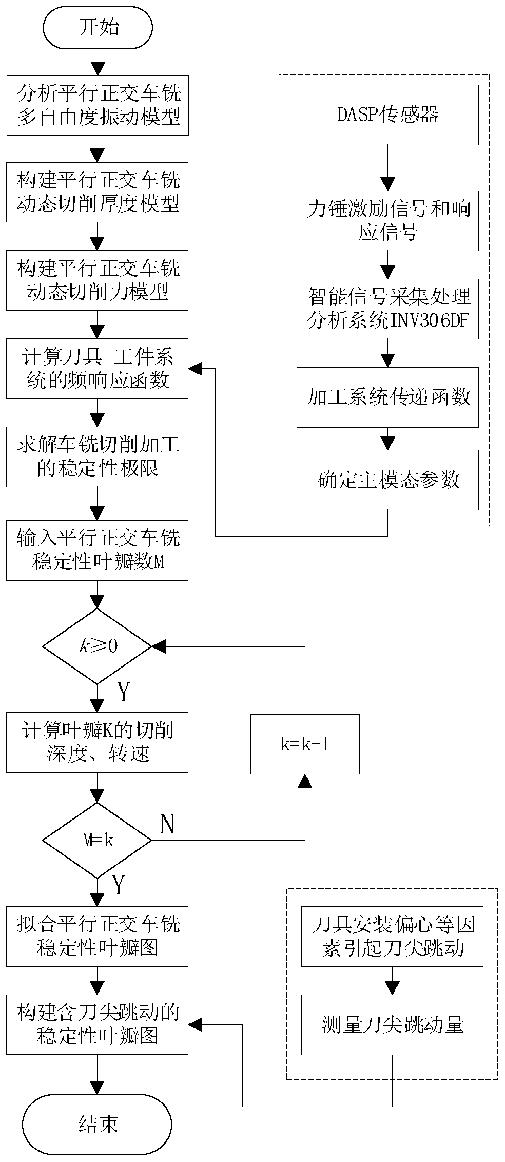
[0060] A method for predicting lobe diagrams of chatter stability in parallel synchronous and orthogonal turning and milling, such as figure 1 As shown, the flow chart of constructing the parallel synchronous orthogonal turning and milling stability lobe diagram, the main steps are as follows:

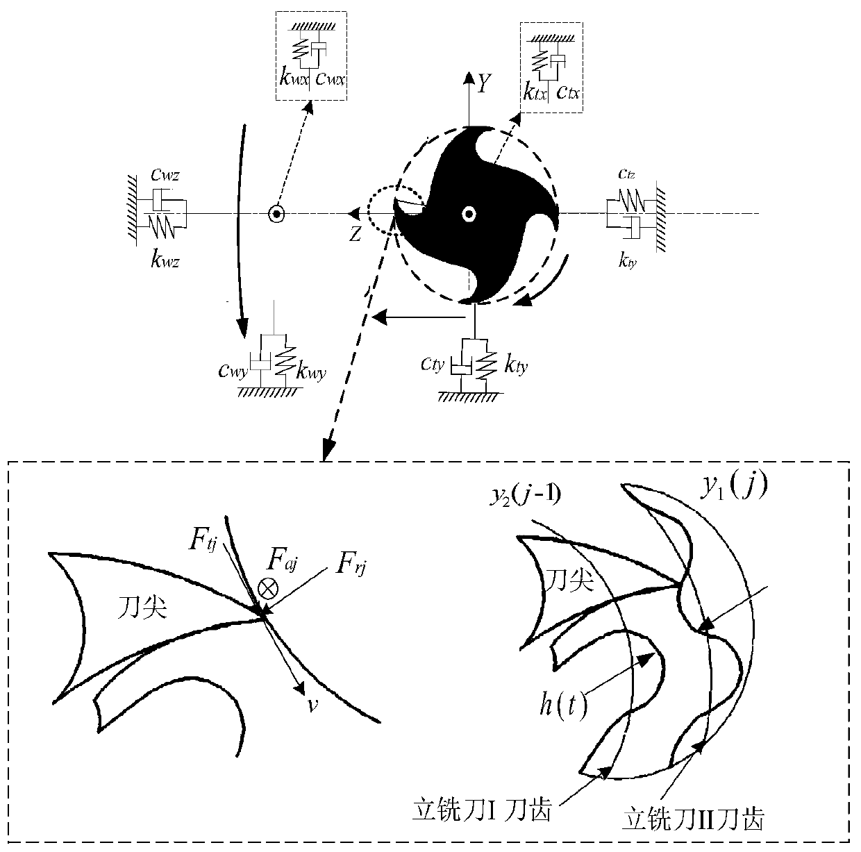
[0061] Step 1: Analyze the multi-degree-of-freedom vibration model of parallel synchronous orthogonal turning and milling;

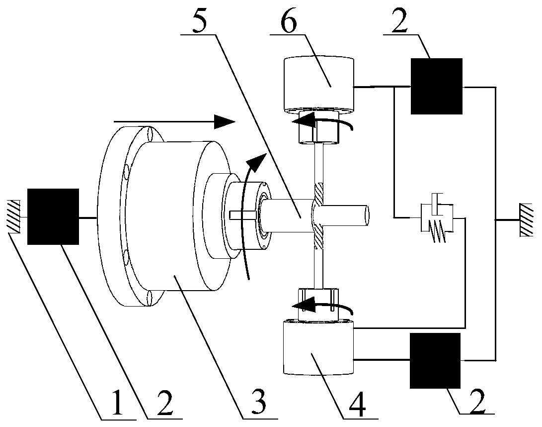
[0062] Such as figure 2 As shown, the parallel synchronous orthogonal turning and milling process consists of two end mills orthogonally turning and milling the outer contour of the workpiece 5, the end mill I4 and the end mill II6 orthogonally turning and milling the surface of the workpiece 5 at the same time, the speed of the tool in the feed direction There is consistency, but the depth of cut can be different for end mill I4 and end ...


PUM


Abstract

The invention discloses a parallel synchronous orthogonal turn-milling flutter stability lobe graph prediction method, and belongs to the technical field of machining and manufacturing. The method isimplemented by the following steps of: sequentially performing steps; analyzing a parallel synchronous orthogonal turn-milling multi-degree-of-freedom vibration model; constructing a dynamic cutting thickness model for parallel synchronous orthogonal turn-milling cutting; constructing a dynamic cutting force model for parallel synchronous orthogonal turn-milling cutting; and calculating a frequency response function of the tool-workpiece system, solving a stability limit of parallel synchronous orthogonal turn-milling cutting machining, constructing a stability lobe graph of parallel synchronous orthogonal turn-milling cutting machining, and constructing a stability lobe graph of parallel synchronous orthogonal turn-milling cutting machining considering tool nose bounce. The parallel synchronous orthogonal turn-milling flutter area and the stable area can be accurately predicted, and the flutter problem in the parallel synchronous orthogonal turn-milling process can be effectively solved.

Description

technical field [0001] The invention belongs to the technical field of mechanical processing and manufacturing, and in particular relates to a method for predicting lobe diagrams of flutter stability in parallel synchronous and orthogonal turning and milling. Background technique [0002] As an advanced processing technology, turning and milling processing technology is widely used in the processing of key components in military and civilian fields such as aerospace, micro-small arms, and precision medical equipment. It has the advantage of completing part processing in one clamping. In order to improve the productivity of turning and milling, it is the key to adopt multi-milling cutters to turn and mill at the same time. Among them, parallel synchronous orthogonal turning and milling is a typical multi-milling cutter turning and milling method. Like other cutting methods, parallel synchronous orthogonal turning and milling process also inevitably produces chatter, which res...

Claims


Application Information

Patent Timeline
IPC IPC(8): G06F30/20G06Q10/04G06F119/14
CPCG06Q10/04
Inventor 金鑫郑中鹏高瑞麟陈武军孙椰望
Owner BEIJING INSTITUTE OF TECHNOLOGYGY
Why Eureka
Try Eureka