
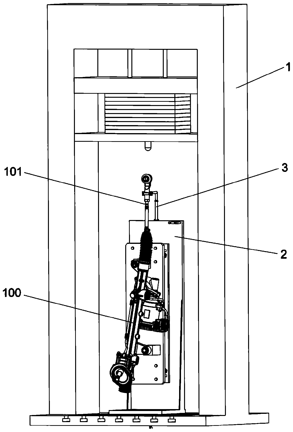
Steering gear impact test bed

An impact test and steering gear technology, which is applied in the field of automobile manufacturing, can solve the problems that the tie rods cannot be guaranteed to be in the same position, the test results are inaccurate, and the free movement of the tie rods cannot be guaranteed during impact, so as to ensure the scientific nature of the test and improve the test accuracy. Effect

Active Publication Date: 2020-02-04
CHINA FIRST AUTOMOBILE
View PDF13 Cites 0 Cited by
  • Summary
  • Abstract
  • Description
  • Claims
  • Application Information

AI Technical Summary

Problems solved by technology

[0005] The above two methods cannot guarantee the free movement of the tie rod during impact, and the impact condition does not match the free movement condition of the actual vehicle during impact. At this time, the impact load will also have a large difference from the impact load of the actual vehicle.
In addition, neither of the two solutions can guarantee that the tie rod is in the same position every time it is impacted
Because the impact is essentially the conversion of potential energy into kinetic energy, the impact load is generated after the impact. The impact load is not only related to the potential energy but also significantly related to the impact duration, and the impact energy, impact position and surface hardness comprehensively affect the impact time. Therefore, it must be guaranteed Only when the tie rod is at the same position for each impact can the repeatability of the impact be guaranteed, otherwise, even under the same potential energy, the measured impact load will vary greatly, and even the impact load with low potential energy will be greater than the impact load with high potential energy , resulting in inaccurate test results

Method used


Image

  • Steering gear impact test bed
  • Steering gear impact test bed
  • Steering gear impact test bed

Examples


Embodiment Construction

[0044] In order to make the technical problems solved by the present invention, the technical solutions adopted and the technical effects achieved clearer, the technical solutions of the present invention will be further described below in conjunction with the accompanying drawings and through specific implementation methods. It should be understood that the specific embodiments described here are only used to explain the present invention, but not to limit the present invention. In addition, it should be noted that, for the convenience of description, only the parts related to the present invention are shown in the drawings but not all of them.

[0045] In the description of the present invention, unless otherwise clearly specified and limited, the terms "connected", "connected" and "fixed" should be understood in a broad sense, for example, it can be a fixed connection, a detachable connection, or an integrated ; It can be a mechanical connection or an electrical connection;...


PUM


Abstract

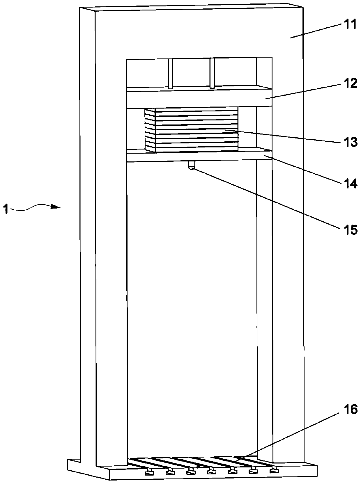
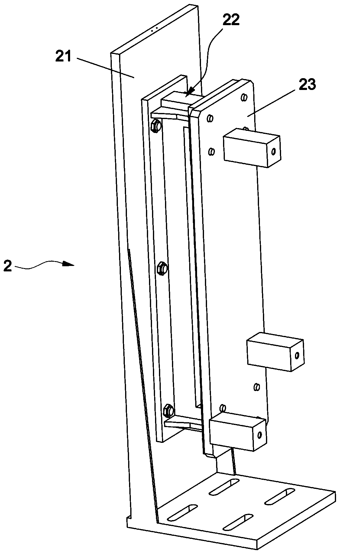
The invention relates to the technical field of automobile manufacturing, and particularly discloses a steering gear impact test bed. The impact test bed comprises a drop hammer impact device, a sample piece fixing device and a pull rod holding device, wherein the sample piece fixing device is arranged below the drop hammer impact device, the sample piece fixing device can fix a steering gear sample piece according to a real vehicle state, and the rigidity of the sample piece fixing device is adjustable, so that the rigidity of the sample piece fixing device is consistent with that of a real vehicle front auxiliary frame system; the pull rod holding device is arranged on the sample piece fixing device, and the pull rod holding device is used for clamping a pull rod of the steering gear sample piece, so that accurate positioning of the pull rod during mounting of the steering gear sample piece can be realized, the positioning precision of the pull rod can be kept before impact, disconnection during impact can be realized to quickly release the pull rod, and free movement of the pull rod when the steering gear sample piece is impacted is realized. According to the steering gear impact test bed, the pull rod of the steering gear sample piece can be fixed at the same position during each impact test, so that the test scientificity and the test precision are ensured.

Description

technical field [0001] The invention relates to the technical field of automobile manufacturing, in particular to a steering gear impact test stand. Background technique [0002] In the design of the damage chain of various parts of the automobile chassis, the steering gear is often damaged before the axle shaft and other load-bearing parts, causing the car to lose its normal steering function (deviation or corner change), so as to tell the user that the car needs to be repaired immediately. Rather than making the axle shaft and other load-bearing parts directly fracture to cause a major accident of car crash. The most common form of damage to the steering gear is curb impact. The weakest link of the steering gear is the connection between the inner and outer tie rods during curb impact. Therefore, impacting the inner and outer tie rods of the steering gear is a necessary chassis test. [0003] The steering gear impact test generally adopts the drop hammer impact form, and ...

Claims


Application Information

Patent Timeline
Patent Type & Authority Applications(China)
IPC IPC(8): G01M7/08
CPCG01M7/08
Inventor 李建华郑树东王志铁张大川王昌林王云龙
Owner CHINA FIRST AUTOMOBILE
Learn More