Mechanical mold with cooling function

A mechanical and functional technology, applied in the field of mechanical molds, can solve the problems of disconnection of water channels, complex cooling effect of water channels, and difficulty in collecting water flow, and achieve the effect of good flexibility and convenient and fast water cooling operation.

Inactive Publication Date: 2020-02-04
XIANYANG NORMAL UNIV
View PDF6 Cites 3 Cited by
  • Summary
  • Abstract
  • Description
  • Claims
  • Application Information

AI Technical Summary

Problems solved by technology

However, the current cooling water channels are usually separate cooling water channels, that is, cooling water channels are provided on the upper and lower mold plates of the mold, or auxiliary cooling is performed by spraying nozzles, etc., which not only causes the problem that multiple water channels are not connected to each other, but also, When cooling, the water path is complicated and the cooling effect is poor, and there is a problem that the water flow is difficult to collect

Method used


Image

  • Mechanical mold with cooling function
  • Mechanical mold with cooling function
  • Mechanical mold with cooling function

Examples


Embodiment Construction

[0024] The technical solutions of the present invention will be further described below in conjunction with the accompanying drawings and specific embodiments.

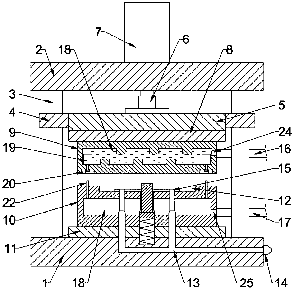
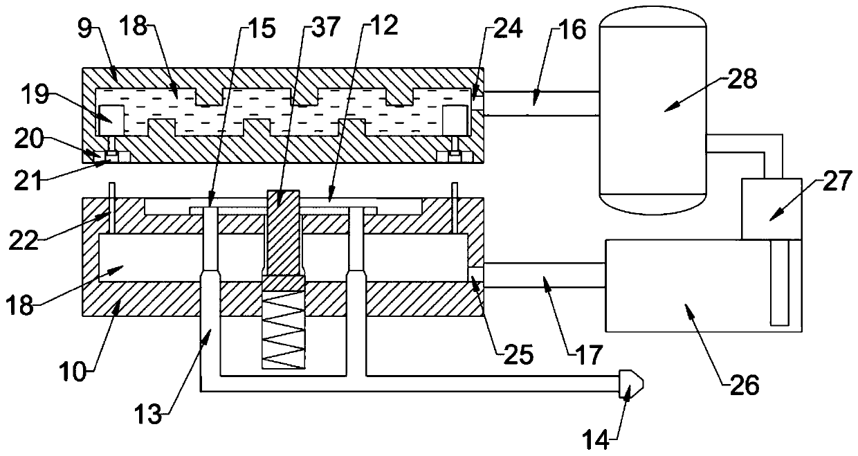
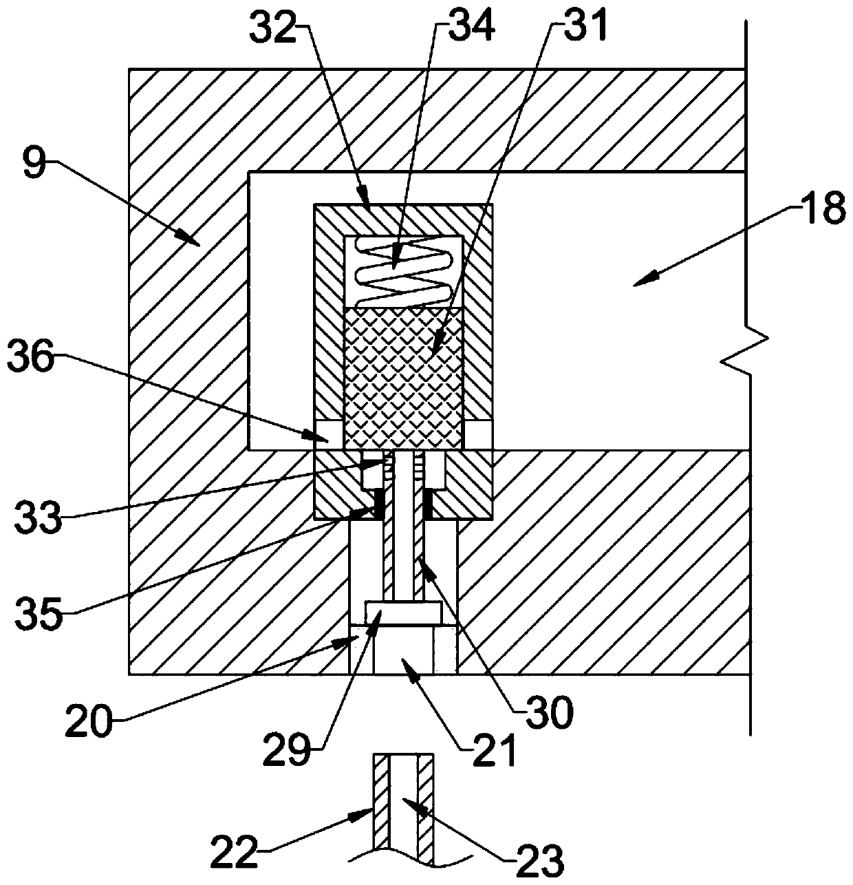
[0025] see Figure 1 ~ Figure 4 , a mechanical mold with a cooling function, including a bottom plate 1, a top plate 2, a connecting rod 3, an upper template 9, a lower template 10, a runner cavity 18, a thimble valve 19 and a thimble 22, the bottom plate 1 and the top plate 2 are connected by connecting rods 3, the top plate 2 is set above the bottom plate 1 and both are horizontally arranged, and the number of connecting rods 3 is at least two. In the embodiment of the present invention, the number of connecting rods 3 is four and Vertically arranged at the four corners of the top plate 2 and the bottom plate 1, the bottom plate 1, the top plate 2 and the connecting rod 3 are connected and fixed to form a stable bracket structure, and the connecting rod 3 between the bottom plate 1 and the top plate 2 There is a gu...


PUM


Abstract

The invention discloses a mechanical mold with a cooling function, and belongs to the field of molds. The problems that cooling water ways of an existing mold do not communicate with one another, andthe cooling effect is poor are solved. The mechanical mold is characterized by comprising an upper mold plate and a lower mold plate, wherein flow channel cavities are formed in the upper mold plate and the lower mold plate; the flow channel cavity in the upper mold plate is connected with a water inlet; the water inlet communicates with an upper cooling water way; the flow channel cavity in the lower mold plate is connected with a water outlet; the water outlet communicates with a lower cooling water way; an ejector pin is arranged on the top of the lower mold plate; an ejector pin valve is arranged at the position, above the ejector pin, of the bottom of the upper mold plate; the flow channel cavities in the upper mold plate and the lower mold plate communicate through the ejector pin and the ejector pin valve; cold water is injected into the upper mold plate; when the upper mold plate and the lower mold plate are closed, the ejector pin of the lower mold plate communicates with theejector pin valve of the upper mold plate, the ejector pin valve is opened, water in the upper mold plate is guided into the lower mold plate, water cooling is achieved; and after the upper mold plateand the lower mold plate are separated, the ejector pin valve is automatically closed, operation is convenient and rapid, and flexibility is good.

Description

technical field [0001] The invention relates to the field of molds, in particular to a mechanical mold with a cooling function. Background technique [0002] Molds are various molds and tools used in industrial production for injection molding, blow molding, extrusion, die-casting or forging forming, smelting and stamping to obtain the required products. Molds are tools used to make shaped objects. Among them, the injection mold is a processing tool used in the mass production of certain complex-shaped parts. Specifically, it refers to injecting the heated and melted material into the mold cavity by high pressure, and after cooling and solidifying, a molded product is obtained. [0003] The mold generally adopts the method of prolonging the cooling time or making more cooling water channels in the core to improve the cooling effect, that is, cooling water channels are set in the cavity and core of the injection mold, and the cooling water is cooled by flowing into the cooli...

Claims


Application Information

Patent Timeline
Patent Type & Authority Applications(China)
IPC IPC(8): B29C45/73
CPCB29C45/7312
Inventor 刘林
Owner XIANYANG NORMAL UNIV
Why Eureka
Try Eureka