
Dual-panel dual-polarized antenna

A dual-polarization, double-panel technology, applied in the direction of antenna coupling, antenna grounding device, antenna grounding switch structure connection, etc., can solve the problems of high feeder impedance, no application value, unfavorable feeder matching, etc., to reduce mutual coupling, Avoid field distribution, low cost effect

Pending Publication Date: 2020-01-31
SHENZHEN EASYDETEK ELECTRONICS CO LTD
View PDF0 Cites 4 Cited by
  • Summary
  • Abstract
  • Description
  • Claims
  • Application Information

AI Technical Summary

Problems solved by technology

[0003] For some cost-sensitive application fields, if further cost reduction is required, it is very attractive to only use double-sided circuit boards to realize dual-polarized antennas. Single-polarized antennas on double-sided circuit boards are very mature technologies, and microstrip feeders pass through Extending into the patch, the two edges of the feeder are divided into slots and isolated from the radiation antenna surface. If it is not inserted into the patch, the impedance of the feed will be very high, which is not conducive to the matching of the 50 ohm feeder.
Since there are slots on both sides of the feeder line, it has little effect on the single-polarized antenna. The orthogonal mode relative to the feeder mode alone affects the electromagnetic field distribution. If the same feeder line is directly introduced on both sides, the coupling of the two modes is very strong. no application value

Method used


Image

  • Dual-panel dual-polarized antenna
  • Dual-panel dual-polarized antenna
  • Dual-panel dual-polarized antenna

Examples


Embodiment 1

[0025] Embodiment 1, the concrete structure of the present invention is as follows:

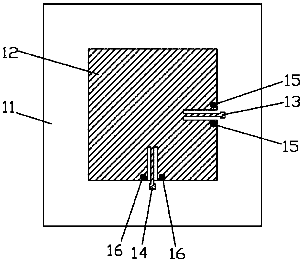
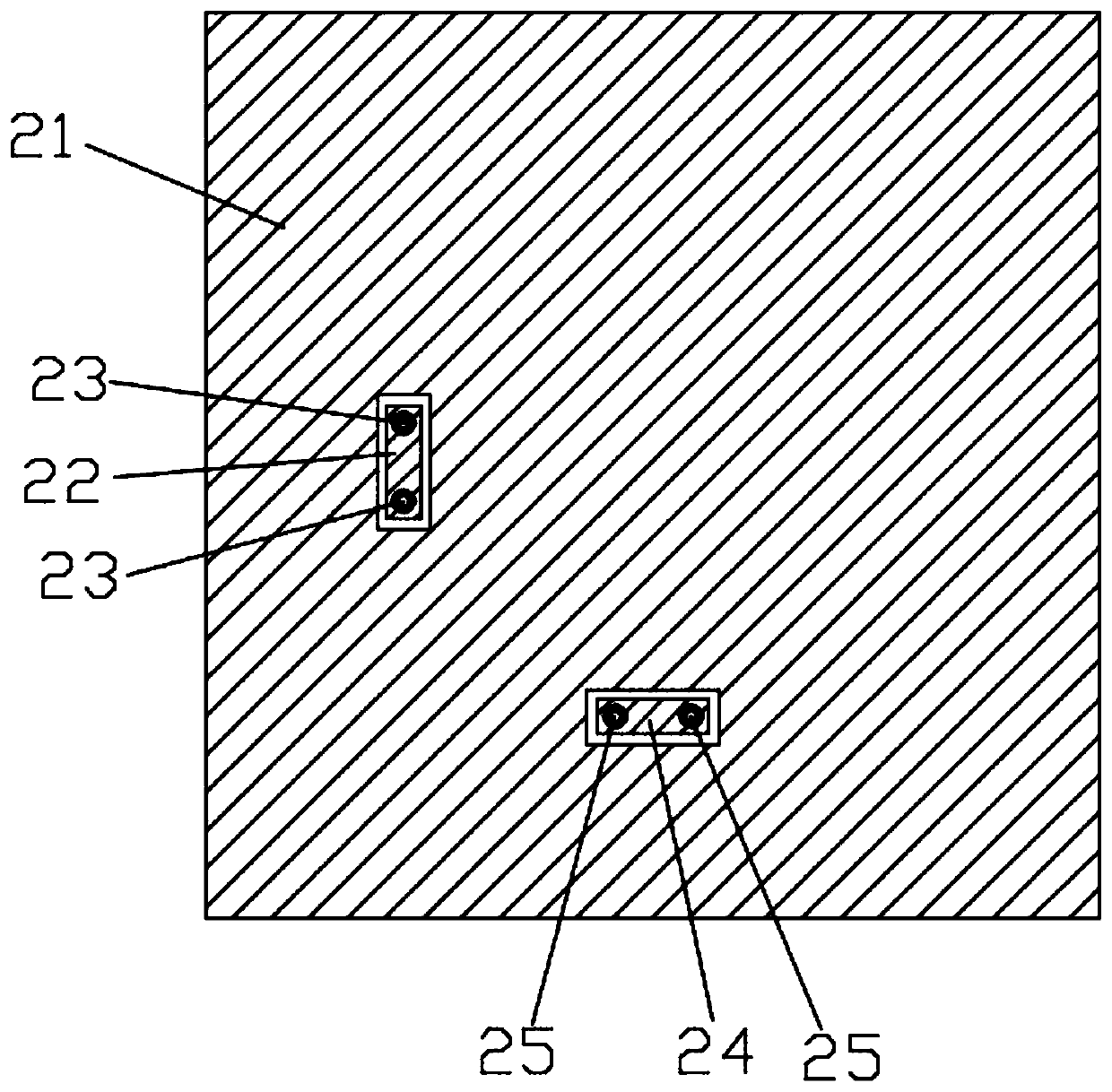
[0026] Please refer to the attached Figure 1-3 , a double-sided dual-polarized antenna of the present invention, including a dielectric substrate 11, a radiating metal patch 12 arranged on one side of the dielectric substrate 11 for radiation, and a grounding metal patch covering the other side of the dielectric substrate 11 Layer 21, in the region of the ground metal layer 21, two first metal regions 22 and second metal regions 24, which are distributed orthogonally and used for freewheeling, are divided. The first metal region 22 and the second metal region 24. Dig metal between the non-segmented area and the non-segmented area to form a non-conductive groove so that the first metal area 22 and the non-segmented area form an isolation structure, and the second metal area 24 and the non-segmented area form an isolation structure ;

[0027] Each of the first metal region 22 and the second ...

Embodiment 2

[0038] In the detection of moving objects in lighting, security, small household appliances and other smart homes, the present invention needs to use the antenna of the microwave sensor of the present invention, specifically a single antenna using a 5.8 GHz ISM frequency band.

Embodiment 3

[0040] Such as Figure 4 as shown, Figure 4 It is a structural schematic diagram of the side with the patch of the double-sided dual-polarized circular patch microstrip antenna of the present invention. The circular patch microstrip antenna replaces the circular radiation metal patch 12 figure 1 In the square radiation metal patch 12, other structures are consistent with those in Embodiment 1.


PUM

PropertyMeasurementUnit
diameteraaaaaaaaaa

Abstract

The invention discloses a dual-panel dual-polarized antenna. The antenna comprises a dielectric substrate, a radiation metal patch which is arranged on one surface of the dielectric substrate and is for radiation, and a grounding metal layer covering the other surface of the dielectric substrate. The antenna is characterized in that a low-cost double-sided circuit board is used for realizing a microstrip feed dual-polarized antenna, mutual coupling of two orthogonal modes is reduced to the maximum extent, a ground plane is not required to switch to a coaxial line for feeding, and a high-pricemulti-layer circuit board is not required to be independently provided with a feed layer. The antenna itself adopts a square or circular patch antenna, 50-ohm impedance matching is achieved by extending feeding into the patch, the patch with the two sides cut by the grooves is connected through the metal through holes, a small part is separated from the complete metal layer of the ground plane toachieve continuity of currents on the two sides of the grooves, and thereby field distribution of a damage mode is avoided, and mutual isolation of the two polarization modes is achieved.

Description

technical field [0001] The invention relates to the technical field of antennas, in particular to a dual-plane dual-polarized antenna. Background technique [0002] At present, the microstrip dual-polarization antenna is mainly implemented by feeding power at two orthogonal positions. Using the orthogonality of the mode, the two feeding ports are isolated from each other. It is required that the introduction of two feed ports cannot affect the field distribution of the two modes, otherwise the isolation will be poor. The traditional feeding method is to use the metal via connected to the radiation patch to pass through the ground plane for coaxial feeding, or use a multi-layer circuit board to make a dedicated feeding network layer. [0003] For some cost-sensitive application fields, if further cost reduction is required, it is very attractive to only use double-sided circuit boards to realize dual-polarized antennas. Single-polarized antennas on double-sided circuit board...

Claims


Application Information

Patent Timeline
Patent Type & Authority Applications(China)
IPC IPC(8): H01Q1/36H01Q1/38H01Q1/48H01Q1/50H01Q1/52
CPCH01Q1/36H01Q1/38H01Q1/50H01Q1/48H01Q1/52
Inventor 金龙李东升吴金晶
Owner SHENZHEN EASYDETEK ELECTRONICS CO LTD
Learn More