A laser projection point coordinate measuring device and its measuring method

A laser projection and measuring device technology, applied in the direction of measuring devices, optical devices, instruments, etc., can solve the problems of difficult installation and use, high production cost, large measurement space, etc., and achieve flexible installation and use, reliable installation and use, and wide application effect of space

Active Publication Date: 2021-12-03
山西易联智控科技有限公司
View PDF7 Cites 0 Cited by
  • Summary
  • Abstract
  • Description
  • Claims
  • Application Information

AI Technical Summary

Problems solved by technology

[0003] At present, pose measurement is faced with problems such as large measurement space, high precision requirements, and complex shape of the measured object. A single pose measurement method is difficult to meet the measurement requirements. The combined measurement method based on the combination of multiple measurement methods has gradually been applied; laser target pose Measurement is a combined measurement method that uses laser targets to cooperate with measuring instruments such as total stations or laser trackers to complete measurements in the entire space
At present, various types of laser targets have been developed at home and abroad. Among them, the foreign laser target guidance systems mainly include the ZED system in the United Kingdom and the VMT system in Germany. The laser targets used are mainly composed of laser CCD cameras, dual-axis inclination angle However, the currently used laser target measurement system uses a large distance between photodiodes in the laser target, low sensing accuracy, and cannot sense and receive multiple laser signals at the same time, and the laser target used is a fixed size. Difficult to install and use, high production cost

Method used


Image

  • A laser projection point coordinate measuring device and its measuring method
  • A laser projection point coordinate measuring device and its measuring method
  • A laser projection point coordinate measuring device and its measuring method

Examples


Embodiment Construction

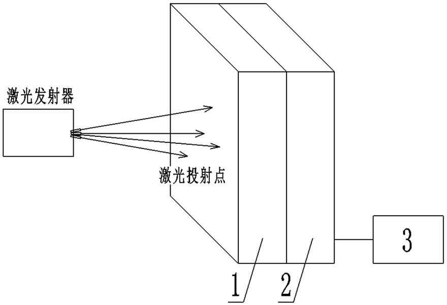
[0050] Such as Figure 1 to Figure 8 As shown, a laser projection point coordinate measuring device of the present invention includes a laser signal receiving unit (1) and a laser signal scanning unit (2) packaged in a casing, and the front side of the laser signal receiving unit (1) is used to receive The laser line beam emitted by the laser transmitter, the laser line beam is irradiated on the shell of the laser signal receiving unit (1) to form a laser irradiation point, and the back of the laser signal receiving unit (1) is connected to the laser signal scanning unit (2) ;

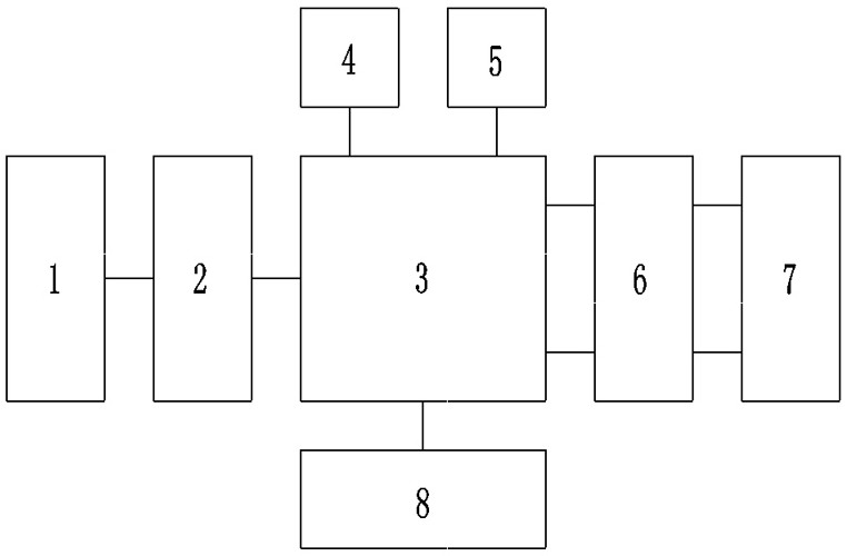
[0051]The signal output terminal of the laser signal scanning unit (2) is connected to the microcontroller (3) through wires, the signal input terminal of the microcontroller (3) is connected to the patch encoder (4), and the microcontroller The signal output terminal of the device (3) is connected to the data storage module (5), and the microcontroller (3) is also bidirectionally connected to the dat...


PUM


Abstract

The invention relates to a laser projection point coordinate measurement device and its measurement method, which belong to the technical field of laser projection point coordinate measurement; the technical problem to be solved is: to provide an improvement of the hardware structure of a laser projection point coordinate measurement device and its measurement method; The technical solution adopted for this technical problem is: including a laser signal receiving unit and a laser signal scanning unit packaged in the casing, the front of the laser signal receiving unit is used to receive the laser beam emitted by the laser transmitter, and the laser beam is irradiated on the A laser irradiation point is formed on the housing of the laser signal receiving unit, and a laser signal scanning unit is connected to the back of the laser signal receiving unit; the signal output end of the laser signal scanning unit is connected to a microcontroller through a wire, and the microcontroller The signal input end of the controller is connected with the chip encoder, and the signal output end of the micro-controller is connected with the data storage module. The invention is applied to the laser projection point coordinate measuring device.

Description

technical field [0001] The invention relates to a laser projection point coordinate measuring device and a measuring method thereof, belonging to the technical field of laser projection point coordinate measurement. Background technique [0002] With the development of science and technology and the continuous improvement of technology, automation and intelligence of equipment in intelligent mines, military shooting training, and shooting competitions have become an inevitable trend. Laser targets are widely used as modern measuring equipment. In the application of intelligent mines, the accuracy of traditional laser targets is not high, and they cannot adapt to the harsh coal mining environment underground. They are easily disturbed by the harsh external environment, unstable and imprecise. With the continuous advancement and development of my country's major basic equipment industry, in the fields of large-scale equipment docking, shield guidance, ship equipment and guidan...

Claims


Application Information

Patent Timeline
Patent Type & Authority Patents(China)
IPC IPC(8): G01B11/00
CPCG01B11/005
Inventor 李锦上田洪现王文林王春进王飙
Owner 山西易联智控科技有限公司
Why Eureka
Try Eureka